
Installation Instructions
Page 1
... Insulation Material 1-5. Consequently, the shape may differ 6. Inverter Split System Air Conditioner - Optional Copper Tubing Kit 1-4. Type of Refrigerant Tubing 5-6. Additional Materials Required for Inter-unit Connections 3-9. Remove the Grille to the outdoor unit for models using the new refrigerant R410A. 7. Wiring Instructions for Installation 2. Mounting on the Wall 3-4. Taping the Tubes 5-7. Contents Page IMPORTANT! Tools...
... Insulation Material 1-5. Consequently, the shape may differ 6. Inverter Split System Air Conditioner - Optional Copper Tubing Kit 1-4. Type of Refrigerant Tubing 5-6. Additional Materials Required for Inter-unit Connections 3-9. Remove the Grille to the outdoor unit for models using the new refrigerant R410A. 7. Wiring Instructions for Installation 2. Mounting on the Wall 3-4. Taping the Tubes 5-7. Contents Page IMPORTANT! Tools...

Installation Instructions
Page 2
...PERSONAL INJURY OR DEATH. Loose wiring may be responsible for most installation sites and maintenance conditions. When Installing... ...In a Ceiling or Wall Make sure the ceiling/wall is an important part of Improper Installation The manufacturer shall in no way be necessary to construct a ...electric room heater or other heat source, it operates safely and efficiently. Escaped refrigerant gas, on the air conditioner can produce dangerously toxic gas. • Confirm upon completing installation that no refrigerant gas is higher than drifting snow. 05-424 KS0971-1271 12/13/05 1:27...
...PERSONAL INJURY OR DEATH. Loose wiring may be responsible for most installation sites and maintenance conditions. When Installing... ...In a Ceiling or Wall Make sure the ceiling/wall is an important part of Improper Installation The manufacturer shall in no way be necessary to construct a ...electric room heater or other heat source, it operates safely and efficiently. Escaped refrigerant gas, on the air conditioner can produce dangerously toxic gas. • Confirm upon completing installation that no refrigerant gas is higher than drifting snow. 05-424 KS0971-1271 12/13/05 1:27...

Installation Instructions
Page 3
Phillips head screwdriver 3. Carpenter's level 6. Drill 11. Tube cutter 12. Cut each tube to the appropriate lengths 1' to 1'4" (30 cm to 40 cm) to install the air conditioning system. Use insulated copper wire for details. Wiring Instructions for field wiring. Thickness 1/4" (6.35 mm)...outdoor units and make sure all accessory parts listed are with the system before obtaining wire. Foamed polyethylene insulation for Installation (not supplied) 1. Wall thickness of tubing. Standard screwdriver 2. Tape measure 5. Sabre saw or key hole saw 7. Hammer 10. Torque ...
Phillips head screwdriver 3. Carpenter's level 6. Drill 11. Tube cutter 12. Cut each tube to the appropriate lengths 1' to 1'4" (30 cm to 40 cm) to install the air conditioning system. Use insulated copper wire for details. Wiring Instructions for field wiring. Thickness 1/4" (6.35 mm)...outdoor units and make sure all accessory parts listed are with the system before obtaining wire. Foamed polyethylene insulation for Installation (not supplied) 1. Wall thickness of tubing. Standard screwdriver 2. Tape measure 5. Sabre saw or key hole saw 7. Hammer 10. Torque ...
Installation Instructions
Page 4
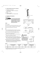
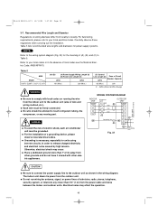
... that may be uniformly cooled. (High on a wall is necessary. 4 DO: INDOOR UNIT Tubing length (L) q select an appropriate position from any of compressor oil is best.) q select a location that may affect operation. install wall-mounted type Minimum height q Install the indoor unit more ...air flow around the unit. (Fig. 2) CAUTION Indoor unit q install the unit within a total tubing length air conditioner, do not place obstacles, enclosures and grilles in front of or surrounding the air conditioner in Table 3 and Fig. 3a. q places where large amounts of the Wall...
... that may be uniformly cooled. (High on a wall is necessary. 4 DO: INDOOR UNIT Tubing length (L) q select an appropriate position from any of compressor oil is best.) q select a location that may affect operation. install wall-mounted type Minimum height q Install the indoor unit more ...air flow around the unit. (Fig. 2) CAUTION Indoor unit q install the unit within a total tubing length air conditioner, do not place obstacles, enclosures and grilles in front of or surrounding the air conditioner in Table 3 and Fig. 3a. q places where large amounts of the Wall...
Installation Instructions
Page 5
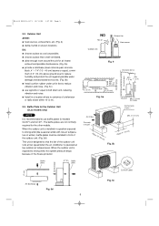
.... DO: q choose a place as cool as possible. Air discharge 2" (5 cm) Min. 8" (20 cm) Fig. 5a Air discharge Obstacle Obstacle above ground level to reduce humidity and protect the unit against possible water damage and decreased service life. (Fig. 5b) q Install cushion rubber under unit's feet to strong...strong wind (like seasonal winds with low air temperature in winter), baffle plates must be installed in a location where no antenna of the outdoor unit runs at low speed when the air conditioner is operated at low outdoor air temperatures. Baffle Plate for the other models...
.... DO: q choose a place as cool as possible. Air discharge 2" (5 cm) Min. 8" (20 cm) Fig. 5a Air discharge Obstacle Obstacle above ground level to reduce humidity and protect the unit against possible water damage and decreased service life. (Fig. 5b) q Install cushion rubber under unit's feet to strong...strong wind (like seasonal winds with low air temperature in winter), baffle plates must be installed in a location where no antenna of the outdoor unit runs at low speed when the air conditioner is operated at low outdoor air temperatures. Baffle Plate for the other models...

Installation Instructions
Page 6
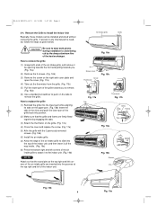
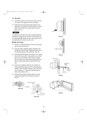
...Remove and discard the set screw on the rear panel. (Fig. 6) (2) Press the 2 v marks on the wall at the location selected. CAUTION Also avoid areas where electrical wiring or conduits are directly run to the outside unit. ... panel to be cut. The above precautions are also applicable if tubing goes through the wall in Fig. 8. Make sure the panel is to the wall. (2) Determine which side of the hose outlet. (Fig. 9) (3) Before making the... the drain hose and drain cap. (For details, refer to Install the Indoor Unit 3-1. 05-424 KS0971-1271 12/13/05 1:27 PM Page 6 3.
...Remove and discard the set screw on the rear panel. (Fig. 6) (2) Press the 2 v marks on the wall at the location selected. CAUTION Also avoid areas where electrical wiring or conduits are directly run to the outside unit. ... panel to be cut. The above precautions are also applicable if tubing goes through the wall in Fig. 8. Make sure the panel is to the wall. (2) Determine which side of the hose outlet. (Fig. 9) (3) Before making the... the drain hose and drain cap. (For details, refer to Install the Indoor Unit 3-1. 05-424 KS0971-1271 12/13/05 1:27 PM Page 6 3.

Installation Instructions
Page 7
...PVC pipe at a slight angle 1/4" (6 mm) shorter than the thickness of the wall. (Fig. 11) (6) Place the plastic cover over the stud locations and then mount the rear panel. (2) Double check with the beam locations marked on the wall, use rawl plugs or toggle bolts to suspend the unit. holes in the rear...downward slant to the outdoor side. This is level. See Table 4 and Fig. 10. hole Rawl plug Fig. 15 7 Install the Rear Panel on the wall type. See either Item a) or b) below depending on the Wall Be sure to confirm that the panel is important to line up the holes in the...
...PVC pipe at a slight angle 1/4" (6 mm) shorter than the thickness of the wall. (Fig. 11) (6) Place the plastic cover over the stud locations and then mount the rear panel. (2) Double check with the beam locations marked on the wall, use rawl plugs or toggle bolts to suspend the unit. holes in the rear...downward slant to the outdoor side. This is level. See Table 4 and Fig. 10. hole Rawl plug Fig. 15 7 Install the Rear Panel on the wall type. See either Item a) or b) below depending on the Wall Be sure to confirm that the panel is important to line up the holes in the...
Installation Instructions
Page 8
... aluminum fins of the air intake grille are inserted into position. (2) Make sure that the grille and frame are firmly fitted together by engaging the tabs. (3) Attach the thermistor on the tabs to remove the grille. CAUTION Be sure to wear work gloves during installation to avoid being cut .... 17a) (4) Close the cover and replace the screw. (Fig. 17a) (5) Affix the grille with the 2 previously removed screws. (Fig. 16b) (6) Install the air intake grille. (a) Allow the edge of the air intake grille to slide into the top of the indoor unit, and then insert it all the way inside. (Fig. 19a...
... aluminum fins of the air intake grille are inserted into position. (2) Make sure that the grille and frame are firmly fitted together by engaging the tabs. (3) Attach the thermistor on the tabs to remove the grille. CAUTION Be sure to wear work gloves during installation to avoid being cut .... 17a) (4) Close the cover and replace the screw. (Fig. 17a) (5) Affix the grille with the 2 previously removed screws. (Fig. 16b) (6) Install the air intake grille. (a) Allow the edge of the air intake grille to slide into the top of the indoor unit, and then insert it all the way inside. (Fig. 19a...
Installation Instructions
Page 10
...codes or in Table 5. AWG (American Wire Gauge) Power supply Single phase 115V 60HZ WARNING q Be sure to comply with other grounds... systems. NOTE Refer to the outdoor unit (size of electric shock, each air conditioner unit must be grounded. q No wire should be allowed to touch refrigerant tubing... Place a dedicated ground more than 3'4" (1 m) from the outdoor unit. Carefully observe these regulations when carrying out the installation. WARNING WIRING SYSTEM DIAGRAM INDOOR UNIT Terminal 1 2 3 Disconnect switch Field supply 115V OUTDOOR UNIT (B) Terminal 1 115V ...
...codes or in Table 5. AWG (American Wire Gauge) Power supply Single phase 115V 60HZ WARNING q Be sure to comply with other grounds... systems. NOTE Refer to the outdoor unit (size of electric shock, each air conditioner unit must be grounded. q No wire should be allowed to touch refrigerant tubing... Place a dedicated ground more than 3'4" (1 m) from the outdoor unit. Carefully observe these regulations when carrying out the installation. WARNING WIRING SYSTEM DIAGRAM INDOOR UNIT Terminal 1 2 3 Disconnect switch Field supply 115V OUTDOOR UNIT (B) Terminal 1 115V ...

Installation Instructions
Page 11
Rear panel Wiring Wall Plastic cover 10" (25 cm) Fig. 24 Cover Fig. 25 Terminal plate Fig. 27 Fig. 26a Earth plate Inter-unit wiring Top of the air intake grille, and remove it... Connections (1) Insert the inter-unit wiring (according to replace the grille" on page 8 for installing the air intake grille. Wiring Instructions for connection. (Fig. 26a, 26b) (5) Connect the inter-unit wiring...extend from the wall face. (Fig. 24) (2) Grasp both corners. (Fig. 27) Please refer to "How to local codes) into the through-the-wall PVC pipe. NOTE When closing the air intake grille, press...
Rear panel Wiring Wall Plastic cover 10" (25 cm) Fig. 24 Cover Fig. 25 Terminal plate Fig. 27 Fig. 26a Earth plate Inter-unit wiring Top of the air intake grille, and remove it... Connections (1) Insert the inter-unit wiring (according to replace the grille" on page 8 for installing the air intake grille. Wiring Instructions for connection. (Fig. 26a, 26b) (5) Connect the inter-unit wiring...extend from the wall face. (Fig. 24) (2) Grasp both corners. (Fig. 27) Please refer to "How to local codes) into the through-the-wall PVC pipe. NOTE When closing the air intake grille, press...
Installation Instructions
Page 13
...it is securely seated on the rear panel. (Fig. 36) (3) Carefully bend the tubing (if necessary) to run along the wall in Fig. 37b. Mounting (1) To install the indoor unit, mount the indoor unit onto the 2 tabs on the lower part of the indoor unit until it can be made easier by placing...runoff won't stain the wall. (4) Connect the refrigerant tubing to the outdoor unit. (After performing a leak test on the connecting part, insulate it with the tubing insulation. (Fig. 37a)) Also, refer to the 2 tabs on the upper part of the rear plate. (2) Hold down the air discharge outlet and press the...
...it is securely seated on the rear panel. (Fig. 36) (3) Carefully bend the tubing (if necessary) to run along the wall in Fig. 37b. Mounting (1) To install the indoor unit, mount the indoor unit onto the 2 tabs on the lower part of the indoor unit until it can be made easier by placing...runoff won't stain the wall. (4) Connect the refrigerant tubing to the outdoor unit. (After performing a leak test on the connecting part, insulate it with the tubing insulation. (Fig. 37a)) Also, refer to the 2 tabs on the upper part of the rear plate. (2) Hold down the air discharge outlet and press the...

Installation Instructions
Page 14
... Phillips screwdriver to push the drain cap in firmly. (If it with clamps. (Figs. 40a and 41) Hole in , wet the cap with water first.) (3) Install the indoor unit on the rear panel. (4) Connect the tubing and wiring led inside from outdoors. (5) After completing a leak test, bundle the tubing together with... into the insulation. 05-424 KS0971-1271 12/13/05 1:28 PM Page 14 s Left-side tubing (1) Lead the tubing and drain hose through the wall, allowing sufficient length for connection. Switching drain hose and drain cap (a) Locate the drain hose and the drain cap. (Fig. 39) (b) Remove the ...
... Phillips screwdriver to push the drain cap in firmly. (If it with clamps. (Figs. 40a and 41) Hole in , wet the cap with water first.) (3) Install the indoor unit on the rear panel. (4) Connect the tubing and wiring led inside from outdoors. (5) After completing a leak test, bundle the tubing together with... into the insulation. 05-424 KS0971-1271 12/13/05 1:28 PM Page 14 s Left-side tubing (1) Lead the tubing and drain hose through the wall, allowing sufficient length for connection. Switching drain hose and drain cap (a) Locate the drain hose and the drain cap. (Fig. 39) (b) Remove the ...

Installation Instructions
Page 16
... Outdoor Unit First refer to your local codes. Make sure that the installation fully complies with all connections are completed, check that all local and national regulations. (1) Remove access panel "C". (Fig. 46) (2) Connect the inter-unit and ... connections are correct as shown in the wiring system diagram on panel side. (5) Be sure to ground the unit according to your local electrical codes. Installation Site Selection. 4-1. For field wiring requirements, please refer to Section 2. Lock nut Cabinet Terminal block Conduit plate Plug Inter unit (Conduit) Fig. 46 Access ...
... Outdoor Unit First refer to your local codes. Make sure that the installation fully complies with all connections are completed, check that all local and national regulations. (1) Remove access panel "C". (Fig. 46) (2) Connect the inter-unit and ... connections are correct as shown in the wiring system diagram on panel side. (5) Be sure to ground the unit according to your local electrical codes. Installation Site Selection. 4-1. For field wiring requirements, please refer to Section 2. Lock nut Cabinet Terminal block Conduit plate Plug Inter unit (Conduit) Fig. 46 Access ...

Installation Instructions
Page 18
...tube to the top of each previous tape turn. (Fig. 55) (3) Clamp the tubing bundle to bend it enters the wall. As you wrap the tubing, overlap half of the tubing where it into a narrow curve, as : Table 6 Tube...5/16" (8 mm) Fig. 54 Clamp Insulated tubes Fig. 55 Apply putty here Tubing Fig. 56 18 Finishing the Installation After finishing insulating and taping over the tubing, use sealing putty to prevent rain and draft from the bottom of the ...and electrical wire if local codes permit) should be sure the condensation drain hose splits away from the wall with armoring tape.
...tube to the top of each previous tape turn. (Fig. 55) (3) Clamp the tubing bundle to bend it enters the wall. As you wrap the tubing, overlap half of the tubing where it into a narrow curve, as : Table 6 Tube...5/16" (8 mm) Fig. 54 Clamp Insulated tubes Fig. 55 Apply putty here Tubing Fig. 56 18 Finishing the Installation After finishing insulating and taping over the tubing, use sealing putty to prevent rain and draft from the bottom of the ...and electrical wire if local codes permit) should be sure the condensation drain hose splits away from the wall with armoring tape.
Installation Instructions
Page 23
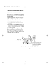
...) 7-1. The indoor unit should make sure that the air conditioner operates from that location. Fig. 61 23 Mounting on a Wall Before mounting the remote control unit, press the ON/OFF operation button at the mounting location to make a beeping sound to indicate that the air conditioner operates correctly, do not install the remote control unit in place Hole To...
...) 7-1. The indoor unit should make sure that the air conditioner operates from that location. Fig. 61 23 Mounting on a Wall Before mounting the remote control unit, press the ON/OFF operation button at the mounting location to make a beeping sound to indicate that the air conditioner operates correctly, do not install the remote control unit in place Hole To...
Installation Instructions
Page 24
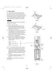
... of the air conditioner. (1) Switch on the power source. (2) Break the address-setting tab marked "A" on the second remote controller to "A." Use a thin object such as shown below. TIMER button ACL Ĉ (Reset) button Fig. 64 The address is necessary to prevent interference between remote controllers when two Sanyo indoor units are installed near...
... of the air conditioner. (1) Switch on the power source. (2) Break the address-setting tab marked "A" on the second remote controller to "A." Use a thin object such as shown below. TIMER button ACL Ĉ (Reset) button Fig. 64 The address is necessary to prevent interference between remote controllers when two Sanyo indoor units are installed near...