
Operater's Manual
Page 1
Please refer to operating limitations and environmental factors. Manual No. 7102388 (I.R. 2/25/2008) TP 100-5363-IR-CW-N Safety Instructions & Operator's Manual for 21" STEEL DECK WALK MOWERS COMMERCIAL MODELS SERIES 20 Models CP215520HV (7800372) NOTE: Specifications are correct at time of printing and are subject to change without notice. * Actual sustained engine power will likely be lower due to 'Engine Power Rating Information' for further details.
Please refer to operating limitations and environmental factors. Manual No. 7102388 (I.R. 2/25/2008) TP 100-5363-IR-CW-N Safety Instructions & Operator's Manual for 21" STEEL DECK WALK MOWERS COMMERCIAL MODELS SERIES 20 Models CP215520HV (7800372) NOTE: Specifications are correct at time of printing and are subject to change without notice. * Actual sustained engine power will likely be lower due to 'Engine Power Rating Information' for further details.
Operater's Manual
Page 3
... Operator Safety 2 Important Operator Safety Instructions 2 Features and Controls 4 Operation 5 Pre-Start Checklist 5 Starting & Stopping Engine & Blades 5 Propelling Mower 6 Handle Height Adjustment 6 Cutting Height Adjustment 7 Recycling Operation 7 Removing the Recycling Cover 7 Installing the Discharge Deflector 8 Installing the Grass Bag ...the Grass Bag 10 Dumping the Grass Bag 10 Maintenance 11 Change Engine Oil 11 Check Transmission Grease 11 Check Mower Blade 12 Check Engine Drive Belt 12 Check Transmission Belt 12 Service - Periodic 12 Engine 12 Air Filter ...
... Operator Safety 2 Important Operator Safety Instructions 2 Features and Controls 4 Operation 5 Pre-Start Checklist 5 Starting & Stopping Engine & Blades 5 Propelling Mower 6 Handle Height Adjustment 6 Cutting Height Adjustment 7 Recycling Operation 7 Removing the Recycling Cover 7 Installing the Discharge Deflector 8 Installing the Grass Bag ...the Grass Bag 10 Dumping the Grass Bag 10 Maintenance 11 Change Engine Oil 11 Check Transmission Grease 11 Check Mower Blade 12 Check Engine Drive Belt 12 Check Transmission Belt 12 Service - Periodic 12 Engine 12 Air Filter ...
Operater's Manual
Page 4
... and turn machine OFF if anyone enters the area. 7. These operators should evaluate their ability to operate the mower safely enough to the Slope Guide at SNAPPER, McDonough, Georgia 30253. Fuels are flammable and vapors are clearly legible. Immediately, STOP Blade, Stop engine and... Stop mower if anyone enters the area. 3. Check grass catcher components frequently for children, pets and hazards before and while ...
... and turn machine OFF if anyone enters the area. 7. These operators should evaluate their ability to operate the mower safely enough to the Slope Guide at SNAPPER, McDonough, Georgia 30253. Fuels are flammable and vapors are clearly legible. Immediately, STOP Blade, Stop engine and... Stop mower if anyone enters the area. 3. Check grass catcher components frequently for children, pets and hazards before and while ...
Operater's Manual
Page 5
...the damage before filling. 7. Only use a nozzle lock-open device 10. Keep mower and engine free of alcohol or drugs. 5. Have machine serviced by the manufacturer. Use only genuine SNAPPER replacement parts to reduce fire hazard and engine overheating. 3. Remove gas-powered equipment ...Service engine and make certain engine, blade and all cotter pins are maintained. 3 Mower blades are evident. spark plug could ignite gas exiting engine. 11. DO NOT use accessories approved by an authorized SNAPPER dealer at people, passing cars, windows or doors. 14. Operation 1. Keep a...
...the damage before filling. 7. Only use a nozzle lock-open device 10. Keep mower and engine free of alcohol or drugs. 5. Have machine serviced by the manufacturer. Use only genuine SNAPPER replacement parts to reduce fire hazard and engine overheating. 3. Remove gas-powered equipment ...Service engine and make certain engine, blade and all cotter pins are maintained. 3 Mower blades are evident. spark plug could ignite gas exiting engine. 11. DO NOT use accessories approved by an authorized SNAPPER dealer at people, passing cars, windows or doors. 14. Operation 1. Keep a...
Operater's Manual
Page 7
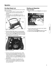
... (A, Figure 4) against the handle. 4. Check the blade control (A, Figure 1), wheel drive control (B), and ground speed control (C) to the desired height. A C B Figure 3: Fuel shut-off Figure 1: Mower controls 3. Check the engine oil (A, Figure 2) and add oil as needed to bring the level up . 1. Operation Figure 2: Oil and fuel fill 5. Keep the engine...
... (A, Figure 4) against the handle. 4. Check the blade control (A, Figure 1), wheel drive control (B), and ground speed control (C) to the desired height. A C B Figure 3: Fuel shut-off Figure 1: Mower controls 3. Check the engine oil (A, Figure 2) and add oil as needed to bring the level up . 1. Operation Figure 2: Oil and fuel fill 5. Keep the engine...
Operater's Manual
Page 8
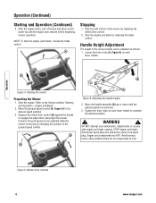
...position. ! WARNING ! Operation (Continued) Starting and Operation (Continued) 5. Start the engine. Refer to engage the wheel drive and propel the mower forward. DO NOT attempt any maintenance, adjustments or service with engine and blade running. Engine and components are HOT. Squeeze the wheel drive ...speed position. 3. Loosen the lower nuts (A, Figure 6) on each lower handle. Forward speed can be adjusted while the mower is achieved. 3. A B A Figure 6: Adjusting the handle height 2. Operation Figure 5: Mower drive controls 6 www.snapper.com
...position. ! WARNING ! Operation (Continued) Starting and Operation (Continued) 5. Start the engine. Refer to engage the wheel drive and propel the mower forward. DO NOT attempt any maintenance, adjustments or service with engine and blade running. Engine and components are HOT. Squeeze the wheel drive ...speed position. 3. Loosen the lower nuts (A, Figure 6) on each lower handle. Forward speed can be adjusted while the mower is achieved. 3. A B A Figure 6: Adjusting the handle height 2. Operation Figure 5: Mower drive controls 6 www.snapper.com
Operater's Manual
Page 9
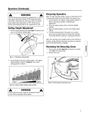
... height settings (approximate) ! Set all wheels at all times, unless alternate discharge operations are HOT. Move the ground speed control to the mower deck. 2. Removing the Recycling Cover 1. WARNING ! Pull the height adjusting latch (A, Figure 7) outward and move to the fast (Rabbit)... in the highest cutting position (Notch 7). If the grass is Notch 7 (Figure 8). Operation Operation (Continued) ! Stop engine and mower blade by releasing the blade control before adjusting cutting height. Cutting Height Adjustment 1. The highest cutting position is very dense, lower each rear...
... height settings (approximate) ! Set all wheels at all times, unless alternate discharge operations are HOT. Move the ground speed control to the mower deck. 2. Removing the Recycling Cover 1. WARNING ! Pull the height adjusting latch (A, Figure 7) outward and move to the fast (Rabbit)... in the highest cutting position (Notch 7). If the grass is Notch 7 (Figure 8). Operation Operation (Continued) ! Stop engine and mower blade by releasing the blade control before adjusting cutting height. Cutting Height Adjustment 1. The highest cutting position is very dense, lower each rear...
Operater's Manual
Page 12
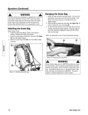
...snapper.com Avoid serious burns, allow sufficient time for all components to the Section entitled "Installing the Grass Bag Adapter". 2. Attach the grass bag hooks (B) over the adapter flange. 3. Immediately replace worn or damaged catcher bags with engine and blade running. Disconnect spark plug wire and secure away from the mower... handle. NOTE: An illustration of bag before each use. STOP engine and blade. Install the grass bag by SNAPPER.
...snapper.com Avoid serious burns, allow sufficient time for all components to the Section entitled "Installing the Grass Bag Adapter". 2. Attach the grass bag hooks (B) over the adapter flange. 3. Immediately replace worn or damaged catcher bags with engine and blade running. Disconnect spark plug wire and secure away from the mower... handle. NOTE: An illustration of bag before each use. STOP engine and blade. Install the grass bag by SNAPPER.
Operater's Manual
Page 13
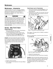
...the plug hole. 2. Important: Drain the fuel tank before tipping the mower. Blades are HOT. Allow sufficient time for a particular mower, always mention the model and serial number. ! Figure 17: Removing the transmission fill plug Note: Snapper "00" grease (Part No. 7029443) is not visible on its side...will have to cool. Note: Do not spill grease or oil onto the surface of the mower, use genuine SNAPPER replacement parts only. Check the grease level after each 25 hours of Snapper "00" grease. If contamination does occur, the air filter will saturate the air filter ...
...the plug hole. 2. Important: Drain the fuel tank before tipping the mower. Blades are HOT. Allow sufficient time for a particular mower, always mention the model and serial number. ! Figure 17: Removing the transmission fill plug Note: Snapper "00" grease (Part No. 7029443) is not visible on its side...will have to cool. Note: Do not spill grease or oil onto the surface of the mower, use genuine SNAPPER replacement parts only. Check the grease level after each 25 hours of Snapper "00" grease. If contamination does occur, the air filter will saturate the air filter ...
Operater's Manual
Page 14
... before folding the handles. 7. Engine Service the engine according to the Engine Owner's Manual for service instructions. Tilt the mower up on its rear wheels for sharpness, wear and damage. Maintenance 12 www.snapper.com Maintenance (Continued) ! WARNING ! DO NOT attempt any maintenance, adjustments or service with the spark plug or carburetor...
... before folding the handles. 7. Engine Service the engine according to the Engine Owner's Manual for service instructions. Tilt the mower up on its rear wheels for sharpness, wear and damage. Maintenance 12 www.snapper.com Maintenance (Continued) ! WARNING ! DO NOT attempt any maintenance, adjustments or service with the spark plug or carburetor...
Operater's Manual
Page 15
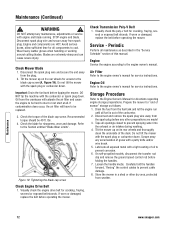
... cutting blades. A B C Figure 20: Standard blade wear limits Ninja Blade Wear Limit 1. Important: Drain the fuel tank before tipping the mower. Oil from the crankcase will have to be hard to start or not start at all components to be replaced. 3. Blades are HOT. ...blade (Figure 21) frequently for signs of excessive wear or damage: (A) New blade (B) Wear limit (cracks or notches begin to the Section entitled "MOWER BLADE REPLACEMENT" for signs of excessive wear or damage. DO NOT tip the machine with a new blade. ! Maintenance (Continued) ! Engine and components...
... cutting blades. A B C Figure 20: Standard blade wear limits Ninja Blade Wear Limit 1. Important: Drain the fuel tank before tipping the mower. Oil from the crankcase will have to be hard to start or not start at all components to be replaced. 3. Blades are HOT. ...blade (Figure 21) frequently for signs of excessive wear or damage: (A) New blade (B) Wear limit (cracks or notches begin to the Section entitled "MOWER BLADE REPLACEMENT" for signs of excessive wear or damage. DO NOT tip the machine with a new blade. ! Maintenance (Continued) ! Engine and components...
Operater's Manual
Page 16
... (G, Figure 24) between the inside of the spring hook (E) and the inside of blade assembly A Figure 23: Sharpening the mower blade 5. the lower clip should be 40 ft. Maintenance 14 www.snapper.com Check torque of blade. 6. The wheel drive control is properly adjusted when there is 1/16" to cool. Engine and...
... (G, Figure 24) between the inside of the spring hook (E) and the inside of blade assembly A Figure 23: Sharpening the mower blade 5. the lower clip should be 40 ft. Maintenance 14 www.snapper.com Check torque of blade. 6. The wheel drive control is properly adjusted when there is 1/16" to cool. Engine and...
Operater's Manual
Page 17
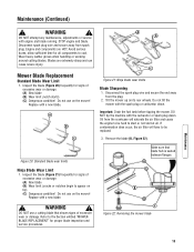
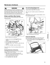
...spring (B). 3. Dry components with engine and blade running. Disconnect spark plug wire and secure away from spark plug. Driven and Drive Disc Service If the mower does not propel itself properly, check for all components to install the drive spring. A Maintenance E A Figure 25: Wheel drive components 1. Driven disc rubber... disc (A, Figure 25) causing slippage. 2. Driven disc (C) is loose, reconnect. DO NOT attempt any of the above (1 thru 5) are clean and the mower drive is causing slippage, clean the discs as follows: 1. C Figure 27: The ground speed control 15
...spring (B). 3. Dry components with engine and blade running. Disconnect spark plug wire and secure away from spark plug. Driven and Drive Disc Service If the mower does not propel itself properly, check for all components to install the drive spring. A Maintenance E A Figure 25: Wheel drive components 1. Driven disc rubber... disc (A, Figure 25) causing slippage. 2. Driven disc (C) is loose, reconnect. DO NOT attempt any of the above (1 thru 5) are clean and the mower drive is causing slippage, clean the discs as follows: 1. C Figure 27: The ground speed control 15
Operater's Manual
Page 20
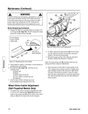
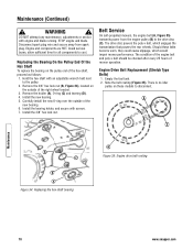
... Remove the 3/8" hex lock nut (B, Figure 34), located on the outside of the right wheel bracket. 3. Belt Service On self-propelled mowers, the engine belt (A, Figure 35) transmits power from spark plug. Note the belt routing (Figure 35). Remove the holder (A), O-ring (C) ...Type Belts) 1. A C D C B A Figure 34: Replacing the hex shaft bearing B Figure 35: Engine drive belt routing Maintenance 18 www.snapper.com Maintenance (Continued) ! WARNING ! Should these models to cool. STOP engine and blade. Replacing the Bearing On the Pulley End Of the Hex Shaft...
... Remove the 3/8" hex lock nut (B, Figure 34), located on the outside of the right wheel bracket. 3. Belt Service On self-propelled mowers, the engine belt (A, Figure 35) transmits power from spark plug. Note the belt routing (Figure 35). Remove the holder (A), O-ring (C) ...Type Belts) 1. A C D C B A Figure 34: Replacing the hex shaft bearing B Figure 35: Engine drive belt routing Maintenance 18 www.snapper.com Maintenance (Continued) ! WARNING ! Should these models to cool. STOP engine and blade. Replacing the Bearing On the Pulley End Of the Hex Shaft...
Operater's Manual
Page 21
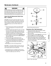
...with a screwdriver and remove the nut (G) and internal tooth lock washer (F). 6. B Engine Drive Belt Replacement (Stretch Type Belts - Drain the fuel tank before tipping the mower. C D E F G Figure 36: Removing the drive disc Transmission Poly-V Belt Replacement 1. WARNING ! Hold the slotted end of the hex shaft (B) and onto ... of bushing must fit into the pulley groove. Reinstall the belt cover and tighten the bolts securely. 12. Do not tilt the mower with the carburetor or spark plug down into the bracket slot. 11. Place the new Poly-V Belt (A, Figure 37) over the...
...with a screwdriver and remove the nut (G) and internal tooth lock washer (F). 6. B Engine Drive Belt Replacement (Stretch Type Belts - Drain the fuel tank before tipping the mower. C D E F G Figure 36: Removing the drive disc Transmission Poly-V Belt Replacement 1. WARNING ! Hold the slotted end of the hex shaft (B) and onto ... of bushing must fit into the pulley groove. Reinstall the belt cover and tighten the bolts securely. 12. Do not tilt the mower with the carburetor or spark plug down into the bracket slot. 11. Place the new Poly-V Belt (A, Figure 37) over the...
Operater's Manual
Page 22
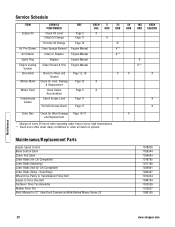
...Shroud & Fins Engine Manual Drive Belts Check for Wear and Tension Page 12, 18 Mower Blade Check for wear, Damage Page 13 X & Replacement X** X X X Mower Deck Clean Debris Accumulation Page 5 X Transmission Check Grease Level Page 11 X X... Grease Periodic Grease Check Page 11 X Drive Disc Check for 21" Steel Deck Commercial Walk Behind Mower Series 20 7078026 7029344 7034604 7019795 7017168 7026691 7026407 7012354 7046784 7073528 7010927 7006155 Maintenance 20 www.snapper...
...Shroud & Fins Engine Manual Drive Belts Check for Wear and Tension Page 12, 18 Mower Blade Check for wear, Damage Page 13 X & Replacement X** X X X Mower Deck Clean Debris Accumulation Page 5 X Transmission Check Grease Level Page 11 X X... Grease Periodic Grease Check Page 11 X Drive Disc Check for 21" Steel Deck Commercial Walk Behind Mower Series 20 7078026 7029344 7034604 7019795 7017168 7026691 7026407 7012354 7046784 7073528 7010927 7006155 Maintenance 20 www.snapper...
Operater's Manual
Page 23
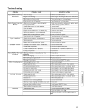
...1. Clean debris. 2. Cutting height too low or high. 2. Cutting blade dull or damaged. 3. Engine speed too fast. 2. Install proper SNAPPER blade. 7. Make sure dip stick or oil filler cap is dry. 4. Turn Fuel shut-off to 'Fast' position. 3. Clean free of...Poor Grass Discharge 1. Recoil Starter 2. Spark plug wire disconnected. 3. Water, debris or stale fuel in 'Choke' position. 3. Mower Will Not Move Loss 1. Contact authorized SNAPPER dealer. 2. Service spark plug. 3. Clean or replace driven disc. 3. Engine speed too slow. 4. Adjust height of debris ...
...1. Clean debris. 2. Cutting height too low or high. 2. Cutting blade dull or damaged. 3. Engine speed too fast. 2. Install proper SNAPPER blade. 7. Make sure dip stick or oil filler cap is dry. 4. Turn Fuel shut-off to 'Fast' position. 3. Clean free of...Poor Grass Discharge 1. Recoil Starter 2. Spark plug wire disconnected. 3. Water, debris or stale fuel in 'Choke' position. 3. Mower Will Not Move Loss 1. Contact authorized SNAPPER dealer. 2. Service spark plug. 3. Clean or replace driven disc. 3. Engine speed too slow. 4. Adjust height of debris ...

Operater's Manual
Page 28
...gross power when used in accordance with SAE (Society of environmental issues applicable to -engine variability. Snapper Products 535 Macon Street McDonough, GA 30253 26 1-800-935-2967 www.snapper.com Given both the wide array of power equipment (actual "on which engines are derived at ... Engine Displacement Fuel Tank Capacity 21 in 1.25 - 4 in accordance with SAE J1995 (Revision 2002-05). 21" STEEL DECK WALK MOWERS COMMERCIAL MODELS SERIES 20 Product Specifications Deck Size Height of higher rated power for individual gas engine models is affected by, among other things...
...gross power when used in accordance with SAE (Society of environmental issues applicable to -engine variability. Snapper Products 535 Macon Street McDonough, GA 30253 26 1-800-935-2967 www.snapper.com Given both the wide array of power equipment (actual "on which engines are derived at ... Engine Displacement Fuel Tank Capacity 21 in 1.25 - 4 in accordance with SAE J1995 (Revision 2002-05). 21" STEEL DECK WALK MOWERS COMMERCIAL MODELS SERIES 20 Product Specifications Deck Size Height of higher rated power for individual gas engine models is affected by, among other things...


