
Operation Manual
Page 2
...at the rear of product specifications for all models. This information will operate the machine, carefully follow the recommended safety practices at Troy-Bilt LLC • P.O. All information in the provided area to do NOT return the machine to performance, power-rating, specifications,...Before setting up , operate and maintain your machine, for purchasing a Chipper/Shredder Vacuum manufactured by Troy-Bilt. Review this machine, you how to ensure your new equipment, please locate the model plate on the web at www.troybilt.com ◊ Call a Customer Support Representative ...
...at the rear of product specifications for all models. This information will operate the machine, carefully follow the recommended safety practices at Troy-Bilt LLC • P.O. All information in the provided area to do NOT return the machine to performance, power-rating, specifications,...Before setting up , operate and maintain your machine, for purchasing a Chipper/Shredder Vacuum manufactured by Troy-Bilt. Review this machine, you how to ensure your new equipment, please locate the model plate on the web at www.troybilt.com ◊ Call a Customer Support Representative ...

Operation Manual
Page 9
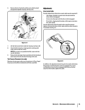
... tank indoors with engine running . Release lever towards nozzle. Never fuel the machine indoors or while the engine is extremely flammable and the vapors are located on slopes. Push adjustment lever out away from 1/2" to 3" ground clearance, to cool for locked or straight ahead operation and when operating on each side...
... tank indoors with engine running . Release lever towards nozzle. Never fuel the machine indoors or while the engine is extremely flammable and the vapors are located on slopes. Push adjustment lever out away from 1/2" to 3" ground clearance, to cool for locked or straight ahead operation and when operating on each side...

Operation Manual
Page 10
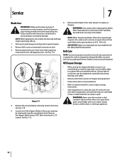
...any adjustments or repairs. Nozzle Door Adjustment Levers The nozzle adjustment levers are located on each front caster wheel. Thrown objects which ricochet can cause serious injury to stop wheel drive. Caster Locks The caster locks are located on top of the controls on the upper handle assembly. Engine Controls ...See the separate engine manual for the location and function of each side of the nozzle door. Release the drive control to position wheel locks. Refer to the Assembly & Set-Up Section...
...any adjustments or repairs. Nozzle Door Adjustment Levers The nozzle adjustment levers are located on each front caster wheel. Thrown objects which ricochet can cause serious injury to stop wheel drive. Caster Locks The caster locks are located on top of the controls on the upper handle assembly. Engine Controls ...See the separate engine manual for the location and function of each side of the nozzle door. Release the drive control to position wheel locks. Refer to the Assembly & Set-Up Section...

Operation Manual
Page 11
... lifting up. Operation 5 Starting Engine WARNING: Keep bystanders, helpers, pets, and children at this point). Do not operate this manual. Make certain drive control is located inside the housing in a normal yard (i.e. Move engine throttle control lever to RUN position. Throttle Control STOP Choke Control Figure 5-1 5. Place one foot on top...
... lifting up. Operation 5 Starting Engine WARNING: Keep bystanders, helpers, pets, and children at this point). Do not operate this manual. Make certain drive control is located inside the housing in a normal yard (i.e. Move engine throttle control lever to RUN position. Throttle Control STOP Choke Control Figure 5-1 5. Place one foot on top...

Operation Manual
Page 12
... a season with a forceful spray of water is not recommended as follows: 1. Stop the engine. Check engine manual for all fasteners and make sure these are located on the front caster wheels to the separate engine manual packed with water. Lubrication 1. Lubricate each use . • Wash bag periodically with your unit. •...
... a season with a forceful spray of water is not recommended as follows: 1. Stop the engine. Check engine manual for all fasteners and make sure these are located on the front caster wheels to the separate engine manual packed with water. Lubrication 1. Lubricate each use . • Wash bag periodically with your unit. •...
Operation Manual
Page 13
... handle, tighten the cable. See Fig. 6-2B. 8. Reattach the discharge chute assembly with the curved side down. 9. If it is corrected. Use the adjustment wheel located in which extend through the impeller housing. Tire Pressure (Pneumatic tires only) Maximum tire pressure under any circumstance is engaged. See Fig. 6-3. NOTE: Be certain...
... handle, tighten the cable. See Fig. 6-2B. 8. Reattach the discharge chute assembly with the curved side down. 9. If it is corrected. Use the adjustment wheel located in which extend through the impeller housing. Tire Pressure (Pneumatic tires only) Maximum tire pressure under any circumstance is engaged. See Fig. 6-3. NOTE: Be certain...
Operation Manual
Page 14
..., make sure to remove an equal amount from each blade and torque hardware to replace or sharpen. IMPORTANT: Make sure that can create a spark. A C B Figure 7-1 4. Locate one of the chipper blades in .lb. Using a light oil or silicone, coat the equipment, especially any type of maintenance on a water heater, furnace, clothes...
..., make sure to remove an equal amount from each blade and torque hardware to replace or sharpen. IMPORTANT: Make sure that can create a spark. A C B Figure 7-1 4. Locate one of the chipper blades in .lb. Using a light oil or silicone, coat the equipment, especially any type of maintenance on a water heater, furnace, clothes...
Operation Manual
Page 20
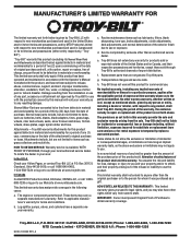
...warranty for commercial use the product. During the period of the warranty, the exclusive remedy is available, WITH PROOF OF PURCHASE, through Troy-Bilt's authorized channels of export distribution. You assume the risk and liability for loss, damage, or injury to you may carry a separate...respective possessions and territories, except those sold . Normal Wear Parts are not limited to items such as : grass collectors and mulch kits. To locate the dealer in this warranty. b. e. f. Replacement parts that are not limited to items such as : batteries, belts, blades, blade ...
...warranty for commercial use the product. During the period of the warranty, the exclusive remedy is available, WITH PROOF OF PURCHASE, through Troy-Bilt's authorized channels of export distribution. You assume the risk and liability for loss, damage, or injury to you may carry a separate...respective possessions and territories, except those sold . Normal Wear Parts are not limited to items such as : grass collectors and mulch kits. To locate the dealer in this warranty. b. e. f. Replacement parts that are not limited to items such as : batteries, belts, blades, blade ...

