
User Manual
Page 6
... MAINBOARD LAYOUT 4 BACK PANEL LAYOUT 4 INSTALLATION 5 CPU 6 CPU Fan: CPU_FAN 6 MEMORY MODULE INSTALLATION 7 Memory Slot: DDR2_SODIMM 7 Available DDR2 SDRAM Configurations 7 CONNECTING THE POWER SUPPLY 8 Pico-ITX 12-Pin Power Connector 8 BACK PANEL PORTS 9 VGA Port 9 RJ45 LAN Port 9 CONNECTORS 10 IDE Connector: IDE 10 Serial ATA Connectors: SATA 11 USB Pin Connector: USB 11 KBMS Connector: PS/2 11 Case Connector: Front Panel 12 Power Switch (PW_BN 12 Reset Switch (RST_SW 12 Power LED (PWR_LED 12 HDD LED (HD_LED 12 Speaker (SPEAK 12 Audio Connector: AUDIO 13 Serial Port...
... MAINBOARD LAYOUT 4 BACK PANEL LAYOUT 4 INSTALLATION 5 CPU 6 CPU Fan: CPU_FAN 6 MEMORY MODULE INSTALLATION 7 Memory Slot: DDR2_SODIMM 7 Available DDR2 SDRAM Configurations 7 CONNECTING THE POWER SUPPLY 8 Pico-ITX 12-Pin Power Connector 8 BACK PANEL PORTS 9 VGA Port 9 RJ45 LAN Port 9 CONNECTORS 10 IDE Connector: IDE 10 Serial ATA Connectors: SATA 11 USB Pin Connector: USB 11 KBMS Connector: PS/2 11 Case Connector: Front Panel 12 Power Switch (PW_BN 12 Reset Switch (RST_SW 12 Power LED (PWR_LED 12 HDD LED (HD_LED 12 Speaker (SPEAK 12 Audio Connector: AUDIO 13 Serial Port...

User Manual
Page 7
BIOS SETUP 19 ENTERING SETUP 20 CONTROL KEYS 21 NAVIGATING THE BIOS MENUS 22 GETTING HELP 23 MAIN MENU 24 Standard CMOS Features 24 Advanced BIOS Features 24 Advanced Chipset Features 24 Integrated Peripherals 24 Power Management Setup 24 PnP/PCI Configurations 24 Frequency/Voltage Control 24 Load Fail-Safe Defaults 25 Load Optimized Defaults 25 Set Supervisor Password 25 Set User Password 25 Save & Exit Setup 25 Exit Without Saving 25 STANDARD CMOS FEATURES 26 Date 26 Time 26 Halt On...
BIOS SETUP 19 ENTERING SETUP 20 CONTROL KEYS 21 NAVIGATING THE BIOS MENUS 22 GETTING HELP 23 MAIN MENU 24 Standard CMOS Features 24 Advanced BIOS Features 24 Advanced Chipset Features 24 Integrated Peripherals 24 Power Management Setup 24 PnP/PCI Configurations 24 Frequency/Voltage Control 24 Load Fail-Safe Defaults 25 Load Optimized Defaults 25 Set Supervisor Password 25 Set User Password 25 Save & Exit Setup 25 Exit Without Saving 25 STANDARD CMOS FEATURES 26 Date 26 Time 26 Halt On...

User Manual
Page 8
... 31 Thermal Management 31 TM2 Bus Ratio 31 TM2 Bus VID 32 C7 CMPXCHGB 32 C7 NoExecute (NX 32 HARD DISK BOOT PRIORITY 33 ADVANCED CHIPSET FEATURES 34 Memory Hole 34 System BIOS Cacheable 34 Video RAM Cacheable 34 Init Display First 34 Select Display Device 35 Panel Type 35 AGP & P2P BRIDGE CONTROL 36 AGP Aperture Size 36 AGP 2.0 Mode 36 AGP Driving Control 37 AGP Fast Write 37...
... 31 Thermal Management 31 TM2 Bus Ratio 31 TM2 Bus VID 32 C7 CMPXCHGB 32 C7 NoExecute (NX 32 HARD DISK BOOT PRIORITY 33 ADVANCED CHIPSET FEATURES 34 Memory Hole 34 System BIOS Cacheable 34 Video RAM Cacheable 34 Init Display First 34 Select Display Device 35 Panel Type 35 AGP & P2P BRIDGE CONTROL 36 AGP Aperture Size 36 AGP 2.0 Mode 36 AGP Driving Control 37 AGP Fast Write 37...
User Manual
Page 9
USB DEVICE SETTING 41 USB 1.0 Controller 41 USB 2.0 Controller 41 USB Operation Mode 41 USB Keyboard Function 42 USB Storage Function 42 No Device 42 POWER MANAGEMENT SETUP 43 ACPI Suspend Type 43 Power Management Option 43 HDD Power Down 43 Suspend Mode 43 Video Off Option 44 Video Off Method 44 MODEM Use IRQ 44 Soft-Off by PWRBTN 44 Run VGABIOS if S3 Resume 44 AC Loss Auto restart 44 WAKEUP EVENT DETECT 45 PS2KB Wakeup Select...
USB DEVICE SETTING 41 USB 1.0 Controller 41 USB 2.0 Controller 41 USB Operation Mode 41 USB Keyboard Function 42 USB Storage Function 42 No Device 42 POWER MANAGEMENT SETUP 43 ACPI Suspend Type 43 Power Management Option 43 HDD Power Down 43 Suspend Mode 43 Video Off Option 44 Video Off Method 44 MODEM Use IRQ 44 Soft-Off by PWRBTN 44 Run VGABIOS if S3 Resume 44 AC Loss Auto restart 44 WAKEUP EVENT DETECT 45 PS2KB Wakeup Select...

User Manual
Page 19
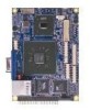
Insert the SODIMM module at a 45 degree angle. Available DDR2 SDRAM Configurations Refer to the table below for DDR2 533 SDRAM memory modules and supports memory sizes up to 1GB. Slot Module Size SODIMM 64MB, 128MB, 256MB, 512MB, 1GB Maximum supported system memory Total 64MB-1GB 64MB-1GB 7 MEMORY MODULE INSTALLATION Installation Memory Slot: DDR2_SODIMM The VIA EPIA-PX Pico-ITX mainboard provides one SODIMM slot for available DDR2 SDRAM configurations on the mainboard. Push the SODIMM module back towards the board until the clips lock the module in place.
Insert the SODIMM module at a 45 degree angle. Available DDR2 SDRAM Configurations Refer to the table below for DDR2 533 SDRAM memory modules and supports memory sizes up to 1GB. Slot Module Size SODIMM 64MB, 128MB, 256MB, 512MB, 1GB Maximum supported system memory Total 64MB-1GB 64MB-1GB 7 MEMORY MODULE INSTALLATION Installation Memory Slot: DDR2_SODIMM The VIA EPIA-PX Pico-ITX mainboard provides one SODIMM slot for available DDR2 SDRAM configurations on the mainboard. Push the SODIMM module back towards the board until the clips lock the module in place.

User Manual
Page 23
... rate, faster than the standard parallel ATA with 133 MB/s (Ultra DMA). The current Serial ATA interface allows up to 4 USB 2.0 ports to connect high-speed USB interface peripherals such as USB HDD, digital cameras, MP3 players, printers, modem and the like. Pin Signal 1 A5V 3 KBCLK 5 MSCLK Pin Signal 2 GND 4 KBDATA 6 MSDATA 1 2 5 6 11 Serial ATA Connectors: SATA The next generation connector supports thin Serial ATA cables for primary internal storage devices.
... rate, faster than the standard parallel ATA with 133 MB/s (Ultra DMA). The current Serial ATA interface allows up to 4 USB 2.0 ports to connect high-speed USB interface peripherals such as USB HDD, digital cameras, MP3 players, printers, modem and the like. Pin Signal 1 A5V 3 KBCLK 5 MSCLK Pin Signal 2 GND 4 KBDATA 6 MSDATA 1 2 5 6 11 Serial ATA Connectors: SATA The next generation connector supports thin Serial ATA cables for primary internal storage devices.
User Manual
Page 29
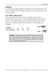
... to pins 1 and 2 afterwards. Setting 1 2 3 Normal Operation ON ON OFF Clear CMOS setting OFF ON ON Normal: 12 3 Clear: 123 WARNING: Except when clearing the RTC RAM, never remove the cap on ; Return the jumper to change the settings of the mainboard functions using the jumpers. Avoid clearing the CMOS while the system is on CMOS Reset jumper default position. Clear CMOS: CMOS Reset The onboard CMOS RAM stores system configuration data and has an onboard battery power supply. it will cause system boot failure...
... to pins 1 and 2 afterwards. Setting 1 2 3 Normal Operation ON ON OFF Clear CMOS setting OFF ON ON Normal: 12 3 Clear: 123 WARNING: Except when clearing the RTC RAM, never remove the cap on ; Return the jumper to change the settings of the mainboard functions using the jumpers. Avoid clearing the CMOS while the system is on CMOS Reset jumper default position. Clear CMOS: CMOS Reset The onboard CMOS RAM stores system configuration data and has an onboard battery power supply. it will cause system boot failure...
User Manual
Page 39
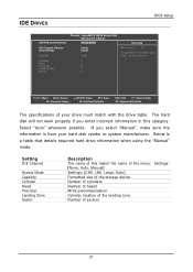
... manufacturer. IDE DRIVES BIOS Setup IDE HDD Auto-Detection Phoenix - The hard disk will not work properly if you select "Manual", make sure the information is a table that details required hard drive information when using the "Manual" mode. Select "Auto" whenever possible. Setting IDE Channel Access Mode Capacity Cylinder Head Precomp Landing Zone Sector Description The name of the menu. AwardBIOS CMOS Setup Utility IDE Channel 0 Master [Press Enter] Item Help IDE Channel 0 Master Access Mode Capacity [Auto] [Auto] 0 MB Menu Level To auto-detect the HDD's size, head...
... manufacturer. IDE DRIVES BIOS Setup IDE HDD Auto-Detection Phoenix - The hard disk will not work properly if you select "Manual", make sure the information is a table that details required hard drive information when using the "Manual" mode. Select "Auto" whenever possible. Setting IDE Channel Access Mode Capacity Cylinder Head Precomp Landing Zone Sector Description The name of the menu. AwardBIOS CMOS Setup Utility IDE Channel 0 Master [Press Enter] Item Help IDE Channel 0 Master Access Mode Capacity [Auto] [Auto] 0 MB Menu Level To auto-detect the HDD's size, head...
User Manual
Page 40
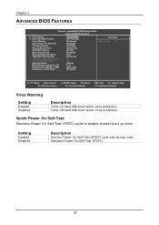
AwardBIOS CMOS Setup Utility Advanced BIOS Features CPU Feature Hard Disk Boot Priority Virus Warning Quick Power On Self Test First Boot Device Second Boot Device Third Boot Device Boot Other Device Boot Up NumLock Status Typematic Rate Setting Typematic Rate (Chars/Sec) Typematic Delay (Msec) Security Option MPS Version Control For OS OS Select For DRAM > 64MB Full Screen LOGO Show [Press Enter] [Press Enter] [Disabled] [Enabled] [CDROM] [Hard Disk] [LS120] [Enabled] [On] [Disabled] 6 250 [Setup] [1.4] [Non-OS2] [Enabled] Item Help Menu Level : Move Enter: Select...
AwardBIOS CMOS Setup Utility Advanced BIOS Features CPU Feature Hard Disk Boot Priority Virus Warning Quick Power On Self Test First Boot Device Second Boot Device Third Boot Device Boot Other Device Boot Up NumLock Status Typematic Rate Setting Typematic Rate (Chars/Sec) Typematic Delay (Msec) Security Option MPS Version Control For OS OS Select For DRAM > 64MB Full Screen LOGO Show [Press Enter] [Press Enter] [Disabled] [Enabled] [CDROM] [Hard Disk] [LS120] [Enabled] [On] [Disabled] 6 250 [Setup] [1.4] [Non-OS2] [Enabled] Item Help Menu Level : Move Enter: Select...
User Manual
Page 41
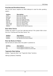
... system fails to load the disk operating system. BIOS Setup First/Second/Third Boot Device Set the boot device sequence as arrow keys Typematic Rate Setting Enables "Typematic Rate" and "Typematic Delay" functions. Setting LS120 Hard Disk CD-ROM ZIP100 USB-FDD USB-ZIP USB-CDROM Legacy LAN Disabled Description Boot from LS-120 drive Boot from the HDD Boot from CD-ROM Boot from ATAPI ZIP drive Boot from USB floppy drive Boot from USB ZIP drive Boot from USB CDROM Boot from network drive Disable the boot device sequence Boot Other Device Enables the system to...
... system fails to load the disk operating system. BIOS Setup First/Second/Third Boot Device Set the boot device sequence as arrow keys Typematic Rate Setting Enables "Typematic Rate" and "Typematic Delay" functions. Setting LS120 Hard Disk CD-ROM ZIP100 USB-FDD USB-ZIP USB-CDROM Legacy LAN Disabled Description Boot from LS-120 drive Boot from the HDD Boot from CD-ROM Boot from ATAPI ZIP drive Boot from USB floppy drive Boot from USB ZIP drive Boot from USB CDROM Boot from network drive Disable the boot device sequence Boot Other Device Enables the system to...
User Manual
Page 42
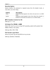
... run BIOS Setup Password prompt appears every time when the computer is required every time the System boots, or only when you are running OS/2 operating system with greater than 64MB of RAM on and when end users try to run BIOS Setup MPS Variation Control for OS Settings: [1.1, 1.4] OS Select For DRAM > 64MB Select OS2 only if you enter Setup. Settings: [Enabled, Disabled] 30 Settings: [Non...
... run BIOS Setup Password prompt appears every time when the computer is required every time the System boots, or only when you are running OS/2 operating system with greater than 64MB of RAM on and when end users try to run BIOS Setup MPS Variation Control for OS Settings: [1.1, 1.4] OS Select For DRAM > 64MB Select OS2 only if you enter Setup. Settings: [Enabled, Disabled] 30 Settings: [Non...
User Manual
Page 49
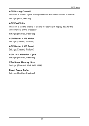
Settings: [Auto, Manual] AGP Fast Write This item is used to auto or manual. Settings: [Enabled, Disabled] AGP Master 1 WS Write Settings:[Enabled, Disabled] AGP Master 1 WS Read Settings:[Enabled, Disabled] AGP 3.0 Calibration Cycle Settings: [Enabled, Disabled] VGA Share Memory Size Settings: [Disabled, 32M, 64M, 128M] Direct Frame Buffer Settings: [Enabled, Disabled] 37 BIOS Setup AGP Driving Control This item is used to signal driving current on AGP cards to enable or disable the caching of display data for the video memory of the processor.
Settings: [Auto, Manual] AGP Fast Write This item is used to auto or manual. Settings: [Enabled, Disabled] AGP Master 1 WS Write Settings:[Enabled, Disabled] AGP Master 1 WS Read Settings:[Enabled, Disabled] AGP 3.0 Calibration Cycle Settings: [Enabled, Disabled] VGA Share Memory Size Settings: [Disabled, 32M, 64M, 128M] Direct Frame Buffer Settings: [Enabled, Disabled] 37 BIOS Setup AGP Driving Control This item is used to signal driving current on AGP cards to enable or disable the caching of display data for the video memory of the processor.
User Manual
Page 53
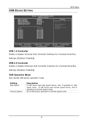
...Controller USB Operation Mode USB Keyboard Function USB Storage Function [Enabled] [Enabled] [High Speed] [Enabled] [Enabled] *** USB Mass Storage Device Boot Setting *** UFDDA USB Floppy UFDDB USB Floppy No Device [Auto mode] No Device [Auto mode] No Device [Auto mode] No Device [Auto mode] No Device [Auto mode] No Device [Auto mode] No Device [Auto mode] No Device [Auto mode] Item Help Menu Level [Enable] or [Disable] Universal Host Controller Interface for Universal Serial Bus : Move Enter: Select F5: Previous Values +/-/PU/PD: Value F10: Save F6: Fail-Safe Defaults...
...Controller USB Operation Mode USB Keyboard Function USB Storage Function [Enabled] [Enabled] [High Speed] [Enabled] [Enabled] *** USB Mass Storage Device Boot Setting *** UFDDA USB Floppy UFDDB USB Floppy No Device [Auto mode] No Device [Auto mode] No Device [Auto mode] No Device [Auto mode] No Device [Auto mode] No Device [Auto mode] No Device [Auto mode] No Device [Auto mode] Item Help Menu Level [Enable] or [Disable] Universal Host Controller Interface for Universal Serial Bus : Move Enter: Select F5: Previous Values +/-/PU/PD: Value F10: Save F6: Fail-Safe Defaults...
User Manual
Page 59
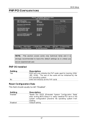
... CMOS Setup Utility PnP / PCI Configurations PNP OS Installed Reset Configuration Data [No] [Disabled] Resources Controlled By x IRQ Resources [Auto(ESCD)] Press Enter PCI/VGA Palette Snoop Assign IRQ For VGA Assign IRQ For USB [Disabled] [Enabled] [Enabled] ** PCI Express relative items ** Maximum ASPM supported Maximum Payload Size [L0s&L1] [4096] Item Help Menu Level Select Yes if you are using a Plug and Play capable operating system. The rest of the cards will be left "Disabled". PNP OS Installed Setting...
... CMOS Setup Utility PnP / PCI Configurations PNP OS Installed Reset Configuration Data [No] [Disabled] Resources Controlled By x IRQ Resources [Auto(ESCD)] Press Enter PCI/VGA Palette Snoop Assign IRQ For VGA Assign IRQ For USB [Disabled] [Enabled] [Enabled] ** PCI Express relative items ** Maximum ASPM supported Maximum Payload Size [L0s&L1] [4096] Item Help Menu Level Select Yes if you are using a Plug and Play capable operating system. The rest of the cards will be left "Disabled". PNP OS Installed Setting...
User Manual
Page 60
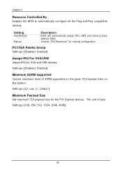
... ASPM supported on the given PCI Express links on the system. Settings: [L0, L0s, L1, L0s&L1] Maximum Payload Size Set maximum TLP payload size for VGA and USB devices. The unit is byte. Chapter 3 Resource Controlled By Enables the BIOS to automatically configure all the Plug-and-Play compatible devices. Settings: [128, 256, 512, 1024, 2048, 4096] 48 Setting Auto(ESCD) Manual Description BIOS will automatically assign IRQ, DMA and memory base...
... ASPM supported on the given PCI Express links on the system. Settings: [L0, L0s, L1, L0s&L1] Maximum Payload Size Set maximum TLP payload size for VGA and USB devices. The unit is byte. Chapter 3 Resource Controlled By Enables the BIOS to automatically configure all the Plug-and-Play compatible devices. Settings: [128, 256, 512, 1024, 2048, 4096] 48 Setting Auto(ESCD) Manual Description BIOS will automatically assign IRQ, DMA and memory base...
User Manual
Page 61
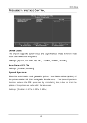
... CMOS Setup Utility Frequency / Voltage Control DRAM Clock/Drive Control Auto Detect PCI Clk Spread Spectrum [Press Enter] [Enabled] [Disabled] Item Help Menu Level BIOS Setup : Move Enter: Select F5: Previous Values +/-/PU/PD: Value F10: Save F6: Fail-Safe Defaults ESC: Exit F1: General Help F7: Optimized Defaults DRAM Clock The chipset supports synchronous and asynchronous mode between host clock and DRAM clock frequency. Settings: [Disabled, 0.20%, 0.25%, 0.35%] 49 Settings: [By SPD, 100 MHz, 133 MHz, 166 MHz, 200MHz, 266MHz] Auto Detect PCI Clk Settings: [Disabled, Enabled...
... CMOS Setup Utility Frequency / Voltage Control DRAM Clock/Drive Control Auto Detect PCI Clk Spread Spectrum [Press Enter] [Enabled] [Disabled] Item Help Menu Level BIOS Setup : Move Enter: Select F5: Previous Values +/-/PU/PD: Value F10: Save F6: Fail-Safe Defaults ESC: Exit F1: General Help F7: Optimized Defaults DRAM Clock The chipset supports synchronous and asynchronous mode between host clock and DRAM clock frequency. Settings: [Disabled, 0.20%, 0.25%, 0.35%] 49 Settings: [By SPD, 100 MHz, 133 MHz, 166 MHz, 200MHz, 266MHz] Auto Detect PCI Clk Settings: [Disabled, Enabled...

User Manual
Page 62
... Menu Level : Move Enter: Select F5: Previous Values +/-/PU/PD: Value F10: Save F6: Fail-Safe Defaults ESC: Exit F1: General Help F7: Optimized Defaults DRAM Clock The chipset supports synchronous and asynchronous mode between host clock and DRAM clock frequency. Settings: [Manual, Auto By SPD] 50 Settings: [By SPD, 100 MHz, 133 MHz, 166 MHz, 200MHz, 266MHz, 333MHz DRAM Timing The value in this field depends on the memory...
... Menu Level : Move Enter: Select F5: Previous Values +/-/PU/PD: Value F10: Save F6: Fail-Safe Defaults ESC: Exit F1: General Help F7: Optimized Defaults DRAM Clock The chipset supports synchronous and asynchronous mode between host clock and DRAM clock frequency. Settings: [Manual, Auto By SPD] 50 Settings: [By SPD, 100 MHz, 133 MHz, 166 MHz, 200MHz, 266MHz, 333MHz DRAM Timing The value in this field depends on the memory...
User Manual
Page 66
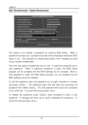
When a password has been set, a password prompt will clear any part of passwords you can be accessed but the BIOS settings cannot be reentered to confirm disabling the password. A supervisor password and a user password. To cancel the process press . AwardBIOS CMOS Setup Utility Standard CMOS Features Advanced BIOS Features Advanced Chipset Features Integrated Peripherals Security Chip Configuration Power Management Setup PnP / PCI Configurations Frequency / Voltage Control Enter Password: Esc : Quit F9 : Menu in length) and press . The password typed now will be confirmed...
When a password has been set, a password prompt will clear any part of passwords you can be accessed but the BIOS settings cannot be reentered to confirm disabling the password. A supervisor password and a user password. To cancel the process press . AwardBIOS CMOS Setup Utility Standard CMOS Features Advanced BIOS Features Advanced Chipset Features Integrated Peripherals Security Chip Configuration Power Management Setup PnP / PCI Configurations Frequency / Voltage Control Enter Password: Esc : Quit F9 : Menu in length) and press . The password typed now will be confirmed...

User Manual
Page 73
Driver Installation Running the Driver Utilities CD To start using the CD, insert the CD into the CD-ROM or DVD-ROM drive. The driver utilities and software menu screen should run automatically, click on the screen. If the CD does not run automatically after closing the CD-ROM or DVD-ROM drive. Then type: "D:\Setup.exe". NOTE: D: might not be the drive letter of the CD-ROM/DVD-ROM in your system. 61 The CD should then appear on the "Start" button and select "Run..."
Driver Installation Running the Driver Utilities CD To start using the CD, insert the CD into the CD-ROM or DVD-ROM drive. The driver utilities and software menu screen should run automatically, click on the screen. If the CD does not run automatically after closing the CD-ROM or DVD-ROM drive. Then type: "D:\Setup.exe". NOTE: D: might not be the drive letter of the CD-ROM/DVD-ROM in your system. 61 The CD should then appear on the "Start" button and select "Run..."
User Manual
Page 74
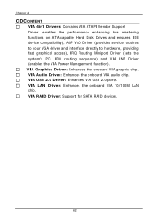
VIA LAN Driver: Enhances the onboard VIA 10/100M LAN chip. VIA RAID Driver: Support for SATA RAID devices. 62 VIA USB 2.0 Driver: Enhances VIA USB 2.0 ports. VIA Audio Driver: Enhances the onboard VIA audio chip. VIA Graphics Driver: Enhances the onboard VIA graphic chip. Chapter 4 CD CONTENT VIA 4in1 Drivers: Contains VIA ATAPI Vendor Support Driver (enables the performance enhancing bus mastering functions on ATA-capable Hard Disk Drives and ensures IDE device compatibility), AGP VxD Driver (provides service routines to your VGA driver and interface directly to hardware, providing fast...
VIA LAN Driver: Enhances the onboard VIA 10/100M LAN chip. VIA RAID Driver: Support for SATA RAID devices. 62 VIA USB 2.0 Driver: Enhances VIA USB 2.0 ports. VIA Audio Driver: Enhances the onboard VIA audio chip. VIA Graphics Driver: Enhances the onboard VIA graphic chip. Chapter 4 CD CONTENT VIA 4in1 Drivers: Contains VIA ATAPI Vendor Support Driver (enables the performance enhancing bus mastering functions on ATA-capable Hard Disk Drives and ensures IDE device compatibility), AGP VxD Driver (provides service routines to your VGA driver and interface directly to hardware, providing fast...
