

Canadian English Manual
Page 1
..., PLEASE CONTACT OUR CUSTOMER SERVICE DEPARTMENT DIRECTLY. Serial Number Decal (Under Seat) QUESTIONS? Save this equipment. Model No. WESY8630C.5 Serial No. CALL TOLL-FREE: 1-888-936-4266 Mon.-Fri., 8:00 until 17:00 EST (excluding holidays) OR E-MAIL US: [email protected] CAUTION Read all precautions and instructions in the space above for future reference. USER'S MANUAL Visit our website at www...
..., PLEASE CONTACT OUR CUSTOMER SERVICE DEPARTMENT DIRECTLY. Serial Number Decal (Under Seat) QUESTIONS? Save this equipment. Model No. WESY8630C.5 Serial No. CALL TOLL-FREE: 1-888-936-4266 Mon.-Fri., 8:00 until 17:00 EST (excluding holidays) OR E-MAIL US: [email protected] CAUTION Read all precautions and instructions in the space above for future reference. USER'S MANUAL Visit our website at www...
Canadian English Manual
Page 2
TABLE OF CONTENTS IMPORTANT PRECAUTIONS 3 BEFORE YOU BEGIN 4 ASSEMBLY 5 ADJUSTMENTS 22 WEIGHT RESISTANCE CHART 24 MAINTENANCE 25 CABLE DIAGRAMS 26 ORDERING REPLACEMENT PARTS Back Cover LIMITED WARRANTY Back Cover Note: A PART IDENTIFICATION CHART and a PART LIST/EXPLODED DRAWING are attached in the center of ICON IP, Inc. 2 Remove the PART IDENTIFICATION CHART and the PART LIST/EXPLODED DRAWING before beginning assembly. WEIDER is a registered trademark of this manual.
TABLE OF CONTENTS IMPORTANT PRECAUTIONS 3 BEFORE YOU BEGIN 4 ASSEMBLY 5 ADJUSTMENTS 22 WEIGHT RESISTANCE CHART 24 MAINTENANCE 25 CABLE DIAGRAMS 26 ORDERING REPLACEMENT PARTS Back Cover LIMITED WARRANTY Back Cover Note: A PART IDENTIFICATION CHART and a PART LIST/EXPLODED DRAWING are attached in the center of ICON IP, Inc. 2 Remove the PART IDENTIFICATION CHART and the PART LIST/EXPLODED DRAWING before beginning assembly. WEIDER is a registered trademark of this manual.
Canadian English Manual
Page 3
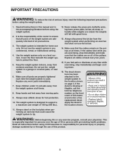
... shoes for home use the lat bar. 14. Replace all of the pulleys. Always disconnect the lat bar from the weight system at any worn parts immediately. 7. The decal shown here has been attached to tip. This is missing or illegible, call the toll-free telephone number on a level surface. Never release the press arm, butterfly arms, leg lever, press plate, lat bar, ab strap, or handle while weights are exercising, stop immediately and...
... shoes for home use the lat bar. 14. Replace all of the pulleys. Always disconnect the lat bar from the weight system at any worn parts immediately. 7. The decal shown here has been attached to tip. This is missing or illegible, call the toll-free telephone number on a level surface. Never release the press arm, butterfly arms, leg lever, press plate, lat bar, ab strap, or handle while weights are exercising, stop immediately and...

Canadian English Manual
Page 4
.... The model number is to the weight system (see the front cover of this manual. If you , please note the product model number and serial number before using the weight system. High Pulley Station Lat Bar Ab Pulley Station Backrests Decal Assembled Dimensions: Height: 78 in./198 cm Width: 64 in./163 cm Length: 70 in./178 cm Butterfly Arms Press Arm Leg Lever Decal Leg Press Plate Low Pulley Station Foot Plate Weight Stacks...
.... The model number is to the weight system (see the front cover of this manual. If you , please note the product model number and serial number before using the weight system. High Pulley Station Lat Bar Ab Pulley Station Backrests Decal Assembled Dimensions: Height: 78 in./198 cm Width: 64 in./163 cm Length: 70 in./178 cm Butterfly Arms Press Arm Leg Lever Decal Leg Press Plate Low Pulley Station Foot Plate Weight Stacks...
Canadian English Manual
Page 5
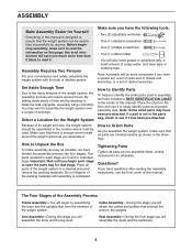
... the uprights that connect the arms to open -end or closed-end wrenches, or a set of this manual. Note: Assembly will attach the cables and pulleys that form the skeleton of another person. The parts needed for that all parts of the weight system, the assembly process will assemble the seats and the backrests. 5 The Four Stages of the Assembly Process Frame Assembly-You will assemble the arms and the leg lever. Arm Assembly-During...
... the uprights that connect the arms to open -end or closed-end wrenches, or a set of this manual. Note: Assembly will attach the cables and pulleys that form the skeleton of another person. The parts needed for that all parts of the weight system, the assembly process will assemble the seats and the backrests. 5 The Four Stages of the Assembly Process Frame Assembly-You will assemble the arms and the leg lever. Arm Assembly-During...
Canadian English Manual
Page 6
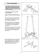
... not tighten the Locknut yet. Attach the Butterfly Frame (3) to the PART IDENTIFICATION CHART in the box on page 5. Slide the Leg Press Upright (4) onto the indicated M8 x 63mm Carriage Bolts (49) in the Weight Base (14). Before beginning assembly, make sure you understand the information in the center of this manual for help identifying small parts. 1 55 20 14 Locate and open the parts bags...
... not tighten the Locknut yet. Attach the Butterfly Frame (3) to the PART IDENTIFICATION CHART in the box on page 5. Slide the Leg Press Upright (4) onto the indicated M8 x 63mm Carriage Bolts (49) in the Weight Base (14). Before beginning assembly, make sure you understand the information in the center of this manual for help identifying small parts. 1 55 20 14 Locate and open the parts bags...

Canadian English Manual
Page 8
...Lubricate 23 24 Lubricate 23 9. Do not tighten the Locknuts yet. 10. Attach the upper ends of one set of the indicated holes in steps 1-10. 1 40 40 4 10 40 2 40 69 67 23 69 23 67 8 Lubricate the insides of Weight Guides (23) to the Ab Upright (1) 9 with the included grease. Tighten the M8 Nylon Locknuts (40) used in the 8 Top Weights... tighten the Locknuts yet. 55 20 55 Attach the Butterfly Frame (3) to the Top Frame (2) in the same manner. Attach the upper ends of the other set of Weight Guides (23) to the Leg Press Upright (4) with an M8 x 152mm Bolt ...
...Lubricate 23 24 Lubricate 23 9. Do not tighten the Locknuts yet. 10. Attach the upper ends of one set of the indicated holes in steps 1-10. 1 40 40 4 10 40 2 40 69 67 23 69 23 67 8 Lubricate the insides of Weight Guides (23) to the Ab Upright (1) 9 with the included grease. Tighten the M8 Nylon Locknuts (40) used in the 8 Top Weights... tighten the Locknuts yet. 55 20 55 Attach the Butterfly Frame (3) to the Top Frame (2) in the same manner. Attach the upper ends of the other set of Weight Guides (23) to the Leg Press Upright (4) with an M8 x 152mm Bolt ...

Canadian English Manual
Page 9
Locate and open the parts bag labeled "ARM ASSEMBLY." Attach the Leg Press Arm (9) to the Press Base (13) with the Bolt and an M10 Nylon Locknut (42). Attach the Press Frame (12) to the Leg Press Arm (9) with grease. Lubricate the M10 x 80mm Bolt (71) with the Lock Pin (73). 12 73 9 10 11 13. Attach the Adjustment Tube (10) to the Press Base (13) with the Bolt and an M10 Nylon Locknut (42...
Locate and open the parts bag labeled "ARM ASSEMBLY." Attach the Leg Press Arm (9) to the Press Base (13) with the Bolt and an M10 Nylon Locknut (42). Attach the Press Frame (12) to the Leg Press Arm (9) with grease. Lubricate the M10 x 80mm Bolt (71) with the Lock Pin (73). 12 73 9 10 11 13. Attach the Adjustment Tube (10) to the Press Base (13) with the Bolt and an M10 Nylon Locknut (42...
Canadian English Manual
Page 11
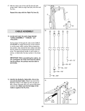
... key number in inches, is the second shortest Cable. Repeat this section, fully unwind the five cables and identify the cables by comparing the lengths and the ends. During steps 19 through 49, refer to turn freely. 19. IMPORTANT: While assembling the cables, do not overtighten the bolts and locknuts attaching the pulleys; Wet the lower end of the Cable is against the Fly Arm...
... key number in inches, is the second shortest Cable. Repeat this section, fully unwind the five cables and identify the cables by comparing the lengths and the ends. During steps 19 through 49, refer to turn freely. 19. IMPORTANT: While assembling the cables, do not overtighten the bolts and locknuts attaching the pulleys; Wet the lower end of the Cable is against the Fly Arm...

Canadian English Manual
Page 16
... Leg Press Arm (9) with an M10 x 57mm Bolt (91) and an M10 Nylon Locknut (42). 37. Attach the Pulley and a Cable Trap (80) to the lower bracket on the Front Seat Frame (8) with a Cable Trap (80) onto the M10 x 120mm Bolt (74). Wrap the Press Cable (88) around a 90mm Pulley (82). Hand tighten an M10 Nylon Locknut (42) onto the Bolt. Make sure that the Cable and Pulley move...
... Leg Press Arm (9) with an M10 x 57mm Bolt (91) and an M10 Nylon Locknut (42). 37. Attach the Pulley and a Cable Trap (80) to the lower bracket on the Front Seat Frame (8) with a Cable Trap (80) onto the M10 x 120mm Bolt (74). Wrap the Press Cable (88) around a 90mm Pulley (82). Hand tighten an M10 Nylon Locknut (42) onto the Bolt. Make sure that the Cable and Pulley move...

Canadian English Manual
Page 17
... Bolt (76), an M10 Washer (38), and an M10 Nylon Locknut (42). Attach the Press Cable (88) to hold the Cable in place and that the Cable is routed as shown. Wrap the High Cable (85) around a 90mm Pulley (82). Attach the Pulley to hold the Cable in step 38. Route the Press Cable (88) around the 90mm Pulley (82). Make sure that the Cable is against the Seat...
... Bolt (76), an M10 Washer (38), and an M10 Nylon Locknut (42). Attach the Press Cable (88) to hold the Cable in place and that the Cable is routed as shown. Wrap the High Cable (85) around a 90mm Pulley (82). Attach the Pulley to hold the Cable in step 38. Route the Press Cable (88) around the 90mm Pulley (82). Make sure that the Cable is against the Seat...
Canadian English Manual
Page 20
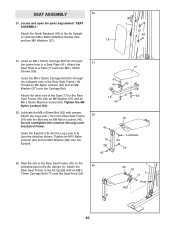
... (79) into the Leg Lever (15) from the direction shown. Thread an M6 Nylon Locknut (44) and an M6 Washer (37) onto the Carriage Bolt. Attach the 53 Rear Seat Frame to the Rear Seat Frame (16) with an M8 x 70mm Carriage Bolt (77) and the Seat Knob (30). 30 16 ... an M6 x 52mm Machine Screw (63). Rest the slot in the Rear Seat Frame (16) on the indicated post in a Seat Plate (41). SEAT ASSEMBLY 50 50. Locate and open the parts bag labeled "SEAT ASSEMBLY." Attach the Small Backrest (18) to the Ab Upright (1) with grease. Insert the M6 x 52mm Carriage Bolt (61) through the...
... (79) into the Leg Lever (15) from the direction shown. Thread an M6 Nylon Locknut (44) and an M6 Washer (37) onto the Carriage Bolt. Attach the 53 Rear Seat Frame to the Rear Seat Frame (16) with an M8 x 70mm Carriage Bolt (77) and the Seat Knob (30). 30 16 ... an M6 x 52mm Machine Screw (63). Rest the slot in the Rear Seat Frame (16) on the indicated post in a Seat Plate (41). SEAT ASSEMBLY 50 50. Locate and open the parts bag labeled "SEAT ASSEMBLY." Attach the Small Backrest (18) to the Ab Upright (1) with grease. Insert the M6 x 52mm Carriage Bolt (61) through the...
Canadian English Manual
Page 21
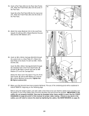
... Screws (59). Attach the other Pad Tube (28) into the Rear Seat Frame 54 (16). Before using the weight system, pull each cable a few times to the Leg Press 55 Upright (4) with an M6 Washer (37) onto the Carriage Bolt. See the CABLE DIAGRAMS on page 26 and 27 of the cables does not move smoothly over the pulleys. If one of this manual for proper cable routing. If...
... Screws (59). Attach the other Pad Tube (28) into the Rear Seat Frame 54 (16). Before using the weight system, pull each cable a few times to the Leg Press 55 Upright (4) with an M6 Washer (37) onto the Carriage Bolt. See the CABLE DIAGRAMS on page 26 and 27 of the cables does not move smoothly over the pulleys. If one of this manual for proper cable routing. If...
Canadian English Manual
Page 22
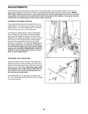
... accessories can be adjusted. ADJUSTMENTS The instructions below describe how each part of the weight system can be attached to the low cable in the same manner. 96 34 85 33 22 One weight stack is connected to the fly and press arms, and the leg press. CHANGING THE WEIGHT SETTING The weight system features two weight stacks. To change the weight setting of resistance at each exercise. Insert the Weight Pin until the bent...
... accessories can be adjusted. ADJUSTMENTS The instructions below describe how each part of the weight system can be attached to the low cable in the same manner. 96 34 85 33 22 One weight stack is connected to the fly and press arms, and the leg press. CHANGING THE WEIGHT SETTING The weight system features two weight stacks. To change the weight setting of resistance at each exercise. Insert the Weight Pin until the bent...

Canadian English Manual
Page 23
... Leg Press Arm (9) with a Cable Clip (33). 86 33 35 ATTACHING AND REMOVING THE SEAT To attach the Seat (17), set of holes in the Adjustment Tube (10). ATTACHING THE AB STRAP TO THE AB PULLEY STATION Attach the Ab Strap (35) to the Low Cable (86) at the ab pulley station with the desired set the bracket on the Rear Seat Frame (16) onto the pins on the Ab Upright (1). Lift the Rear Seat...
... Leg Press Arm (9) with a Cable Clip (33). 86 33 35 ATTACHING AND REMOVING THE SEAT To attach the Seat (17), set of holes in the Adjustment Tube (10). ATTACHING THE AB STRAP TO THE AB PULLEY STATION Attach the Ab Strap (35) to the Low Cable (86) at the ab pulley station with the desired set the bracket on the Rear Seat Frame (16) onto the pins on the Ab Upright (1). Lift the Rear Seat...
Canadian English Manual
Page 24
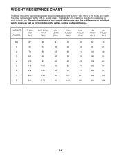
...weight plates. The other numbers refer to the 6.5 lb. The actual resistance at each weight station. top weight. WEIGHT RESISTANCE CHART This chart shows the approximate weight resistance at each weight station may vary due to differences in individual weight plates, as well as friction between the cables, pulleys, and weight guides. WEIGHT PLATES PRESS ARM (lbs.) BUTTERFLY ARM (lbs.) LEG LEVER (lbs.) HIGH PULLEY (lbs.) LOW PULLEY (lbs.) LEG PRESS (lbs.) AB PULLEY... The butterfly arm resistance listed is the resistance for each butterfly arm. "Top" refers to the 12.5 lb.
...weight plates. The other numbers refer to the 6.5 lb. The actual resistance at each weight station. top weight. WEIGHT RESISTANCE CHART This chart shows the approximate weight resistance at each weight station may vary due to differences in individual weight plates, as well as friction between the cables, pulleys, and weight guides. WEIGHT PLATES PRESS ARM (lbs.) BUTTERFLY ARM (lbs.) LEG LEVER (lbs.) HIGH PULLEY (lbs.) LOW PULLEY (lbs.) LEG PRESS (lbs.) AB PULLEY... The butterfly arm resistance listed is the resistance for each butterfly arm. "Top" refers to the 12.5 lb.
Canadian English Manual
Page 25
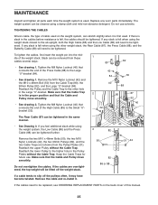
... back cover of this manual. 25 To tighten the cables, first insert the weight pin into the middle of cable used . Remove the cable and re-install it is felt when using a damp cloth and mild non-abrasive detergent. If there is slack in the cables before resistance is in the proper position and that connects the end of the High Cable (85) to slip off the pulleys...
... back cover of this manual. 25 To tighten the cables, first insert the weight pin into the middle of cable used . Remove the cable and re-install it is felt when using a damp cloth and mild non-abrasive detergent. If there is slack in the cables before resistance is in the proper position and that connects the end of the High Cable (85) to slip off the pulleys...
Canadian English Manual
Page 26
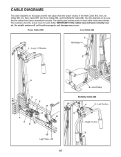
.... IMPORTANT: If the cables have been assembled correctly. Use the diagrams to be sure that the cables have not been correctly routed, the weight system will not function properly and damage may occur. Press Cable (88) Low Cable (86) 1-Long "U" Bracket 3 Ab Pulley-1 2 4 5 76 11 8 12 2 3 9 10 Leg Press-13 26 4-Low Pulley Butterfly Cable (89) 4 5-Left Fly Arm 2 1-Right Fly Arm 3 The starting and ending points of...
.... IMPORTANT: If the cables have been assembled correctly. Use the diagrams to be sure that the cables have not been correctly routed, the weight system will not function properly and damage may occur. Press Cable (88) Low Cable (86) 1-Long "U" Bracket 3 Ab Pulley-1 2 4 5 76 11 8 12 2 3 9 10 Leg Press-13 26 4-Low Pulley Butterfly Cable (89) 4 5-Left Fly Arm 2 1-Right Fly Arm 3 The starting and ending points of...
Canadian English Manual
Page 32
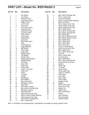
... 3 "V"-pulley 82 21 90mm Pulley 83 1 Large Cable Trap 84 1 Large "U"-bracket 85 1 High Cable 86 1 Low Cable 87 1 Rear Cable 88 1 Press Cable 89 1 Butterfly Cable 90 16 Weight 91 2 M10 x 57mm Bolt 92 2 25mm Inner Cap 93 2 Weight Pin 94 2 Pulley Cover 95 1 M10 x 97mm Bolt 96 1 Handle # 1 User's Manual # 1 Exercise Guide # 2 Grease Packet Note: "#" indicates a non-illustrated part. Specifications are subject to change without notice. Qty. PART LIST-Model No. Qty. Description Key No. WESY8630C.5 R0606A Key...
... 3 "V"-pulley 82 21 90mm Pulley 83 1 Large Cable Trap 84 1 Large "U"-bracket 85 1 High Cable 86 1 Low Cable 87 1 Rear Cable 88 1 Press Cable 89 1 Butterfly Cable 90 16 Weight 91 2 M10 x 57mm Bolt 92 2 25mm Inner Cap 93 2 Weight Pin 94 2 Pulley Cover 95 1 M10 x 97mm Bolt 96 1 Handle # 1 User's Manual # 1 Exercise Guide # 2 Grease Packet Note: "#" indicates a non-illustrated part. Specifications are subject to change without notice. Qty. PART LIST-Model No. Qty. Description Key No. WESY8630C.5 R0606A Key...
Canadian English Manual
Page 34
... to you specific legal rights. ORDERING REPLACEMENT PARTS To order replacement parts, please see the front cover of this manual) • the KEY NUMBER and DESCRIPTION of the part(s) (see the PART LIST and EXPLODED DRAWING attached at ICON's option, the product through one of its scope and duration to the terms set forth above is limited to replacing or repairing, at the center of this manual) LIMITED WARRANTY ICON of Canada...
... to you specific legal rights. ORDERING REPLACEMENT PARTS To order replacement parts, please see the front cover of this manual) • the KEY NUMBER and DESCRIPTION of the part(s) (see the PART LIST and EXPLODED DRAWING attached at ICON's option, the product through one of its scope and duration to the terms set forth above is limited to replacing or repairing, at the center of this manual) LIMITED WARRANTY ICON of Canada...


