
Canadian English Manual
Page 2
TABLE OF CONTENTS IMPORTANT PRECAUTIONS 3 BEFORE YOU BEGIN 4 ASSEMBLY 5 ADJUSTMENTS 22 WEIGHT RESISTANCE CHART 24 MAINTENANCE 25 CABLE DIAGRAMS 26 ORDERING REPLACEMENT PARTS Back Cover LIMITED WARRANTY Back Cover Note: A PART IDENTIFICATION CHART and a PART LIST/EXPLODED DRAWING are attached in the center of ICON IP, Inc. 2 WEIDER is a registered trademark of this manual. Remove the PART IDENTIFICATION CHART and the PART LIST/EXPLODED DRAWING before beginning assembly.
TABLE OF CONTENTS IMPORTANT PRECAUTIONS 3 BEFORE YOU BEGIN 4 ASSEMBLY 5 ADJUSTMENTS 22 WEIGHT RESISTANCE CHART 24 MAINTENANCE 25 CABLE DIAGRAMS 26 ORDERING REPLACEMENT PARTS Back Cover LIMITED WARRANTY Back Cover Note: A PART IDENTIFICATION CHART and a PART LIST/EXPLODED DRAWING are attached in the center of ICON IP, Inc. 2 WEIDER is a registered trademark of this manual. Remove the PART IDENTIFICATION CHART and the PART LIST/EXPLODED DRAWING before beginning assembly.
Canadian English Manual
Page 11
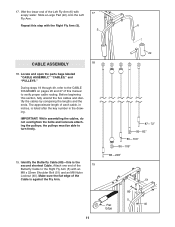
... open the parts bags labeled "CABLE ASSEMBLY," "CABLES," and "PULLEYS." IMPORTANT: While assembling the cables, do not overtighten the bolts and locknuts attaching the pulleys; During steps 19 through 49, refer to the CABLE DIAGRAMS on pages 26 and 27 of the 19 Butterfly Cable to turn freely. 19. Repeat... this manual to verify proper cable routing. the pulleys must be able to the Right Fly Arm (5) with an...
... open the parts bags labeled "CABLE ASSEMBLY," "CABLES," and "PULLEYS." IMPORTANT: While assembling the cables, do not overtighten the bolts and locknuts attaching the pulleys; During steps 19 through 49, refer to the CABLE DIAGRAMS on pages 26 and 27 of the 19 Butterfly Cable to turn freely. 19. Repeat... this manual to verify proper cable routing. the pulleys must be able to the Right Fly Arm (5) with an...
Canadian English Manual
Page 21
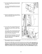
... in the Front Seat Frame (8). Attach the other Pad Tube (28) into the Rear Seat Frame 54 (16). The use of this manual for proper cable routing. Slide two Foam Pads (29) onto the ends of the Seat (17) to the Front Seat Frame (8) with two M6 x 16mm Screws (59). Insert... M6 Nylon Locknut (44). 17 8 41 60 59 37 64 44 57. Before using the weight system, pull each cable a few times to remove the slack by tightening the cables. See the CABLE DIAGRAMS on page 26 and 27 of the remaining parts will need to be explained in ADJUSTMENTS, beginning on page 25...
... in the Front Seat Frame (8). Attach the other Pad Tube (28) into the Rear Seat Frame 54 (16). The use of this manual for proper cable routing. Slide two Foam Pads (29) onto the ends of the Seat (17) to the Front Seat Frame (8) with two M6 x 16mm Screws (59). Insert... M6 Nylon Locknut (44). 17 8 41 60 59 37 64 44 57. Before using the weight system, pull each cable a few times to remove the slack by tightening the cables. See the CABLE DIAGRAMS on page 26 and 27 of the remaining parts will need to be explained in ADJUSTMENTS, beginning on page 25...
Canadian English Manual
Page 26
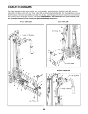
...High Cable (85), the Low Cable (86), the Rear Cable (87), the Press Cable (88), and the Butterfly Cable (89). IMPORTANT: If the cables have not been correctly routed, the weight system will not function properly and damage may occur. CABLE DIAGRAMS The cable diagrams on... this page and the next page show the proper route for each cable have been assembled correctly. The numbers show the proper routing of each cable. Press Cable (88) Low Cable (86) 1-Long "U" Bracket 3 Ab Pulley-1...
...High Cable (85), the Low Cable (86), the Rear Cable (87), the Press Cable (88), and the Butterfly Cable (89). IMPORTANT: If the cables have not been correctly routed, the weight system will not function properly and damage may occur. CABLE DIAGRAMS The cable diagrams on... this page and the next page show the proper route for each cable have been assembled correctly. The numbers show the proper routing of each cable. Press Cable (88) Low Cable (86) 1-Long "U" Bracket 3 Ab Pulley-1...


