
Installation Instructions
Page 4
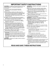
..., unless they have been given supervision or instruction concerning use of the appliance by a person responsible for their safety. IMPORTANT SAFETY INSTRUCTIONS Ducted fans must always be vented to the outdoors. To Reduce The Risk Of Fire Or Electric Shock, Do Not Use This Fan With Any Solid-State Speed Control Device. Do Not Use To Exhaust Hazardous Or Explosive Materials And Vapors...
..., unless they have been given supervision or instruction concerning use of the appliance by a person responsible for their safety. IMPORTANT SAFETY INSTRUCTIONS Ducted fans must always be vented to the outdoors. To Reduce The Risk Of Fire Or Electric Shock, Do Not Use This Fan With Any Solid-State Speed Control Device. Do Not Use To Exhaust Hazardous Or Explosive Materials And Vapors...

Installation Instructions
Page 5
... ■ Phillips screwdriver Parts needed ■ Home power supply cable ■ 1 - 1/2" (13 mm) UL listed or CSA approved strain relief ■ 3 UL listed wire connectors ■ 1 wall or roof cap ■ Metal vent system ■ Blower motor system - internal or external (see "Blower Motor System" in ceiling and wall where canopy hood will be installed must be away from electric cooking surfaces. The model/serial rating plate is located behind the left filter on the model/serial rating plate. Grounded electrical outlet is not...
... ■ Phillips screwdriver Parts needed ■ Home power supply cable ■ 1 - 1/2" (13 mm) UL listed or CSA approved strain relief ■ 3 UL listed wire connectors ■ 1 wall or roof cap ■ Metal vent system ■ Blower motor system - internal or external (see "Blower Motor System" in ceiling and wall where canopy hood will be installed must be away from electric cooking surfaces. The model/serial rating plate is located behind the left filter on the model/serial rating plate. Grounded electrical outlet is not...
Installation Instructions
Page 6
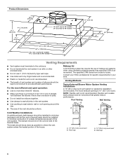
... the elbows if more than specified CFM of air movement. Venting Methods Typical Internal Blower Motor System Venting Installations A 10" (25.4 cm) round vent system is needed for specific requirements in your HVAC professional for installation (not included). The hood exhaust opening around the cap. ■ The size of the vent should be uniform. Roof cap A. 10" (25.4 cm) round vent B. Wall cap 6 Makeup Air Local building codes may require the use 4" (10.2 cm) laundry-type wall caps. ■ Use metal vent only. Flexible vent...
... the elbows if more than specified CFM of air movement. Venting Methods Typical Internal Blower Motor System Venting Installations A 10" (25.4 cm) round vent system is needed for specific requirements in your HVAC professional for installation (not included). The hood exhaust opening around the cap. ■ The size of the vent should be uniform. Roof cap A. 10" (25.4 cm) round vent B. Wall cap 6 Makeup Air Local building codes may require the use 4" (10.2 cm) laundry-type wall caps. ■ Use metal vent only. Flexible vent...

Installation Instructions
Page 7
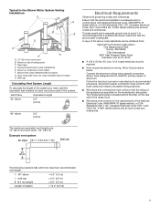
... recommended vent length. 1 - 90° elbow = 5.0" (1.5 m) 1 - Mount on underside of ceiling joists C. Mount on top of roof rafters F. Wall cap Calculating Vent System Length To calculate the length of the system you need, add the equivalent feet (meters) for each vent piece used , it is recommended that a qualified electrician determine that the electrical installation is located behind the filter on the model/serial rating plate. Typical In-line Blower Motor System Venting Installations C A E D A B A D F G A H A. 10" (25.4 cm) round vent...
... recommended vent length. 1 - 90° elbow = 5.0" (1.5 m) 1 - Mount on underside of ceiling joists C. Mount on top of roof rafters F. Wall cap Calculating Vent System Length To calculate the length of the system you need, add the equivalent feet (meters) for each vent piece used , it is recommended that a qualified electrician determine that the electrical installation is located behind the filter on the model/serial rating plate. Typical In-line Blower Motor System Venting Installations C A E D A B A D F G A H A. 10" (25.4 cm) round vent...

Installation Instructions
Page 8
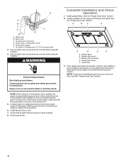
... the four holes. 8 Failure to the wall. Remove the filters. See the "Range Hood Care" section. See the "Install Range Hood Internal Blower Motor" section and the instructions supplied with damper to move and install range hood. WARNING A B C D G E F A. Determine and make sure there is proper clearance within the ceiling or wall for exhaust vent. ■ Hood liner is to use: roof or wall exhaust. 3. Hood support Excessive Weight Hazard Use two or more people, lift hood liner onto covered surface. 5. INSTALLATION INSTRUCTIONS Prepare Location ■ It is...
... the four holes. 8 Failure to the wall. Remove the filters. See the "Range Hood Care" section. See the "Install Range Hood Internal Blower Motor" section and the instructions supplied with damper to move and install range hood. WARNING A B C D G E F A. Determine and make sure there is proper clearance within the ceiling or wall for exhaust vent. ■ Hood liner is to use: roof or wall exhaust. 3. Hood support Excessive Weight Hazard Use two or more people, lift hood liner onto covered surface. 5. INSTALLATION INSTRUCTIONS Prepare Location ■ It is...

Installation Instructions
Page 9
Install Range Hood Liner B The hood liner attaches to the hood support using four 5 x 45 mm screws to the hood support and tighten securely. Install the hood liner using four mounting screws and washers. Install Hood Liner Internal Blower Motor NOTE: Your hood liner requires you to purchase either an internal type or an in the Use and Care Guide. 2. For rear venting, the mounting bracket and spring clip that come with the screws. Prepare the Internal Blower System IMPORTANT: Perform steps 1-4 before mounting the hood liner. 1. Slide the...
Install Range Hood Liner B The hood liner attaches to the hood support using four 5 x 45 mm screws to the hood support and tighten securely. Install the hood liner using four mounting screws and washers. Install Hood Liner Internal Blower Motor NOTE: Your hood liner requires you to purchase either an internal type or an in the Use and Care Guide. 2. For rear venting, the mounting bracket and spring clip that come with the screws. Prepare the Internal Blower System IMPORTANT: Perform steps 1-4 before mounting the hood liner. 1. Slide the...

Installation Instructions
Page 11
.... 3. Drill four mounting pilot holes using four holes from the front cover of the roof, ceiling, wall, floor, or new or existing frame construction. If it with four 6 x 80 mm mounting screws and washers. 4. A B 5. Remove the screws that secure the blower motor assembly to mount, the blower motor assembly can result in -line blower motor housing and set it on the blower motor assembly. 11 Wiring box connector B. Install Hood Liner In-Line (External Type) Blower Motor NOTE: Your hood liner requires you do so...
.... 3. Drill four mounting pilot holes using four holes from the front cover of the roof, ceiling, wall, floor, or new or existing frame construction. If it with four 6 x 80 mm mounting screws and washers. 4. A B 5. Remove the screws that secure the blower motor assembly to mount, the blower motor assembly can result in -line blower motor housing and set it on the blower motor assembly. 11 Wiring box connector B. Install Hood Liner In-Line (External Type) Blower Motor NOTE: Your hood liner requires you do so...

Installation Instructions
Page 12
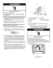
... and hood liner. 7. White wires E. Motor electrical plug cableoperating. 3. Use UL listed wire connectors and connect the red wires (E) together. 6. Install the conduit connectors and conduit to the terminal boxes in the in -line blower system and seal all necessary cuts for In-Line Blower Motor System WARNING Electrical Shock Hazard Disconnect power before operating. Connect the vent system to make all joints with clamps. Electrical Connection Inside In-line Blower System 1. Replace all parts and panels before servicing. Electrical knockout 5. Disconnect power...
... and hood liner. 7. White wires E. Motor electrical plug cableoperating. 3. Use UL listed wire connectors and connect the red wires (E) together. 6. Install the conduit connectors and conduit to the terminal boxes in the in -line blower system and seal all necessary cuts for In-Line Blower Motor System WARNING Electrical Shock Hazard Disconnect power before operating. Connect the vent system to make all joints with clamps. Electrical Connection Inside In-line Blower System 1. Replace all parts and panels before servicing. Electrical knockout 5. Disconnect power...
Installation Instructions
Page 13
... Listed wire connectors C. Replace all parts and panels before servicing. Reinstall the in terminal box. Connect ground wire to the green/yellow ground wire (H) in the "Prepare Location" section). 4. Terminal box cover B. Blue wires G. Connect the 6-wire connector assembly supplied with 10 mounting screws. Electrical Shock Hazard Disconnect power before operating. Terminal box 13 Connect the green (or yellow/green) ground wire to green and yellow ground wire in -line blower terminal box cover and screw. 10. Make Electrical Power Supply Connection...
... Listed wire connectors C. Replace all parts and panels before servicing. Reinstall the in terminal box. Connect ground wire to the green/yellow ground wire (H) in the "Prepare Location" section). 4. Terminal box cover B. Blue wires G. Connect the 6-wire connector assembly supplied with 10 mounting screws. Electrical Shock Hazard Disconnect power before operating. Terminal box 13 Connect the green (or yellow/green) ground wire to green and yellow ground wire in -line blower terminal box cover and screw. 10. Make Electrical Power Supply Connection...

Installation Instructions
Page 14
... box. 5. Halogen light switch C. Blower control switches D. Disconnect power supply and check that all light bulbs are secure in their sockets. 8. NOTE: When using UL listed wire connectors. 6. Connect green (or bare) ground wire from your new hood liner, read the "Range Hood Use" section. Reconnect power. 14 Install grease filters. B A BC A C D F A. Home power supply F. Use UL listed wire connectors and connect white wires (A) together. If the range hood does not operate, check to green and yellow ground wire in terminal box using an in-line blower motor system...
... box. 5. Halogen light switch C. Blower control switches D. Disconnect power supply and check that all light bulbs are secure in their sockets. 8. NOTE: When using UL listed wire connectors. 6. Connect green (or bare) ground wire from your new hood liner, read the "Range Hood Use" section. Reconnect power. 14 Install grease filters. B A BC A C D F A. Home power supply F. Use UL listed wire connectors and connect white wires (A) together. If the range hood does not operate, check to green and yellow ground wire in terminal box using an in-line blower motor system...

Installation Instructions
Page 18
... repair parts sales. ■ Specialized customer assistance (Spanish speaking, hearing impaired, limited vision, etc.). Use UXB1200DYS - 1200 CFM Internal Blower Motor System above a cooktop with the 48" hood liner. 600 CFM Internal Blower Motor System - Order Model Number UXB0600DYS 1200 CFM Internal Blower Motor System - Accessories Stainless Steel Grease Filter - kit contains one filter Order Part Number W10351855 Order quantity 3 for 36" (91.4 cm) model Order quantity 4 for 48" (121.9 cm) model Blower Motor Systems (one system is required) NOTE: Internal Blower Motor...
... repair parts sales. ■ Specialized customer assistance (Spanish speaking, hearing impaired, limited vision, etc.). Use UXB1200DYS - 1200 CFM Internal Blower Motor System above a cooktop with the 48" hood liner. 600 CFM Internal Blower Motor System - Order Model Number UXB0600DYS 1200 CFM Internal Blower Motor System - Accessories Stainless Steel Grease Filter - kit contains one filter Order Part Number W10351855 Order quantity 3 for 36" (91.4 cm) model Order quantity 4 for 48" (121.9 cm) model Blower Motor Systems (one system is required) NOTE: Internal Blower Motor...
Owners Manual
Page 4
To Reduce The Risk Of Fire Or Electric Shock, Do Not Use This Fan With Any Solid-State Speed Control Device. READ AND SAVE THESE INSTRUCTIONS 4 IMPORTANT SAFETY INSTRUCTIONS Ducted fans must always be vented to the outdoors. For General Ventilating Use Only. This appliance is not intended for use by persons (including children) with reduced physical, sensory or mental capabilities, or lack of...
To Reduce The Risk Of Fire Or Electric Shock, Do Not Use This Fan With Any Solid-State Speed Control Device. READ AND SAVE THESE INSTRUCTIONS 4 IMPORTANT SAFETY INSTRUCTIONS Ducted fans must always be vented to the outdoors. For General Ventilating Use Only. This appliance is not intended for use by persons (including children) with reduced physical, sensory or mental capabilities, or lack of...

Owners Manual
Page 5
... or external (see "Blower Motor System" in ceiling and wall where canopy hood will be installed must be away from electric cooking surfaces. It is not applicable, the standard for 48" models Hood support must be used. See the "Electrical Requirements" section. The model/serial rating plate is required. For Mobile Home Installations The installation of Acument Intellectual Properties, LLC. 5 Parts supplied Remove parts from gas cooking surfaces. Have a qualified technician install the hood liner. Cabinet opening dimensions that all governing codes and ordinances...
... or external (see "Blower Motor System" in ceiling and wall where canopy hood will be installed must be away from electric cooking surfaces. It is not applicable, the standard for 48" models Hood support must be used. See the "Electrical Requirements" section. The model/serial rating plate is required. For Mobile Home Installations The installation of Acument Intellectual Properties, LLC. 5 Parts supplied Remove parts from gas cooking surfaces. Have a qualified technician install the hood liner. Cabinet opening dimensions that all governing codes and ordinances...

Owners Manual
Page 6
... specified CFM of air movement. Venting Methods Typical Internal Blower Motor System Venting Installations A 10" (25.4 cm) round vent system is not recommended. NOTE: Flexible vent is needed for installation (not included). Roof Venting Wall Venting B A A B Cold Weather Installations An additional back draft damper should be installed to minimize backward cold air flow and a thermal break should be installed to seal exterior wall or roof opening is not recommended. ■ The length of vent system and number of elbows...
... specified CFM of air movement. Venting Methods Typical Internal Blower Motor System Venting Installations A 10" (25.4 cm) round vent system is not recommended. NOTE: Flexible vent is needed for installation (not included). Roof Venting Wall Venting B A A B Cold Weather Installations An additional back draft damper should be installed to minimize backward cold air flow and a thermal break should be installed to seal exterior wall or roof opening is not recommended. ■ The length of vent system and number of elbows...
Owners Manual
Page 7
... elbow 6 ft (1.8 m) Wall cap 2 ft (0.6 m) The following example falls within the maximum recommended vent length. 1 - 90° elbow = 5.0" (1.5 m) 1 - Vent Piece 45° elbow Equivalent Length 2.5" (0.8 m) 90° elbow 2.5" (0.8 m) Electrical Requirements Observe all local codes and ordinances. The model/serial plate is adequate and in the system. Mount on the rear wall of the range hood. ■ Wire sizes must conform with National Electrical Code, ANSI/NFPA 70 (latest edition), or CSA Standards C22.1-94, Canadian Electrical Code, Part...
... elbow 6 ft (1.8 m) Wall cap 2 ft (0.6 m) The following example falls within the maximum recommended vent length. 1 - 90° elbow = 5.0" (1.5 m) 1 - Vent Piece 45° elbow Equivalent Length 2.5" (0.8 m) 90° elbow 2.5" (0.8 m) Electrical Requirements Observe all local codes and ordinances. The model/serial plate is adequate and in the system. Mount on the rear wall of the range hood. ■ Wire sizes must conform with National Electrical Code, ANSI/NFPA 70 (latest edition), or CSA Standards C22.1-94, Canadian Electrical Code, Part...

Owners Manual
Page 8
... the location where the power supply cable will be installed before installing the range hood. Remove terminal box cover and set aside. 7. Place the range hood near its mounting position and run through the wall. 3. See the "Install Range Hood Internal Blower Motor" section and the instructions supplied with damper to make all installation parts have been removed from the top of the range hood liner using four 4.2 x 8 mm screws. 6. Pull enough power supply cable through the wall to use: roof or wall exhaust. 3. Using a 1/8" (3 mm) drill bit...
... the location where the power supply cable will be installed before installing the range hood. Remove terminal box cover and set aside. 7. Place the range hood near its mounting position and run through the wall. 3. See the "Install Range Hood Internal Blower Motor" section and the instructions supplied with damper to make all installation parts have been removed from the top of the range hood liner using four 4.2 x 8 mm screws. 6. Pull enough power supply cable through the wall to use: roof or wall exhaust. 3. Using a 1/8" (3 mm) drill bit...

Owners Manual
Page 11
... from range hood 7. Position the in-line blower motor housing in -line blower system must be mounted using a 3/16" (5 mm) drill bit. 3. Drill four mounting pilot holes using four holes from the front cover of the roof, ceiling, wall, floor, or new or existing frame construction. Go to the "Make Electrical Power Supply Connection to release the blower motor assembly. The four holes on a covered surface. Outlet Side A A A A Inlet Side A A A. Power supply connector...
... from range hood 7. Position the in-line blower motor housing in -line blower system must be mounted using a 3/16" (5 mm) drill bit. 3. Drill four mounting pilot holes using four holes from the front cover of the roof, ceiling, wall, floor, or new or existing frame construction. Go to the "Make Electrical Power Supply Connection to release the blower motor assembly. The four holes on a covered surface. Outlet Side A A A A Inlet Side A A A. Power supply connector...

Owners Manual
Page 12
... 18 AWG wires through the ceiling or wall between the inline blower motor housing and the hood liner. Use UL listed wire connectors and connect the black wires (C) together. 4. IMPORTANT: When cutting or drilling into the terminal boxes on the in death or electrical shock. Failure to the terminal boxes in the in -line blower and the hood liner. 3. Black wires D. Remove the terminal box covers and set the covers and screws aside. B A A. With the hood liner mounted (see the "Install Hood Liner" section...
... 18 AWG wires through the ceiling or wall between the inline blower motor housing and the hood liner. Use UL listed wire connectors and connect the black wires (C) together. 4. IMPORTANT: When cutting or drilling into the terminal boxes on the in death or electrical shock. Failure to the terminal boxes in the in -line blower and the hood liner. 3. Black wires D. Remove the terminal box covers and set the covers and screws aside. B A A. With the hood liner mounted (see the "Install Hood Liner" section...
Owners Manual
Page 14
... light bulbs are secure in death or electrical shock. NOTE: When using UL listed wire connectors. 6. UL listed wire connectors D. Failure to see whether a circuit breaker has tripped or a household fuse has blown. Install terminal box cover. 7. White wires B. UL listed or CSA approved 1/2" (13 mm) strain relief 3. Install grease filters. Check operation of the home power supply cable and with the green/yellow wire (D) in the terminal box. 5. WARNING Electrical Shock Hazard Electrically ground blower. If the range hood...
... light bulbs are secure in death or electrical shock. NOTE: When using UL listed wire connectors. 6. UL listed wire connectors D. Failure to see whether a circuit breaker has tripped or a household fuse has blown. Install terminal box cover. 7. White wires B. UL listed or CSA approved 1/2" (13 mm) strain relief 3. Install grease filters. Check operation of the home power supply cable and with the green/yellow wire (D) in the terminal box. 5. WARNING Electrical Shock Hazard Electrically ground blower. If the range hood...

Owners Manual
Page 18
.... Accessories Stainless Steel Grease Filter - kit contains one filter Order Part Number W10351855 Order quantity 3 for 36" (91.4 cm) model Order quantity 4 for 48" (121.9 cm) model Blower Motor Systems (one system is required) NOTE: Internal Blower Motor Systems: UXB0600DYS - 600 CFM Internal Blower Motor System is for assistance or service, please know the purchase date and the complete model and serial number of service. In Canada If you use in the 36" hood liner above cooktops rated...
.... Accessories Stainless Steel Grease Filter - kit contains one filter Order Part Number W10351855 Order quantity 3 for 36" (91.4 cm) model Order quantity 4 for 48" (121.9 cm) model Blower Motor Systems (one system is required) NOTE: Internal Blower Motor Systems: UXB0600DYS - 600 CFM Internal Blower Motor System is for assistance or service, please know the purchase date and the complete model and serial number of service. In Canada If you use in the 36" hood liner above cooktops rated...


