
Hardware Installation Guide
Page 1
Catalyst 2960 Switch Hardware Installation Guide March 2010 Americas Headquarters Cisco Systems, Inc. 170 West Tasman Drive San Jose, CA 95134-1706 USA http://www.cisco.com Tel: 408 526-4000 800 553-NETS (6387) Fax: 408 527-0883 Text Part Number: OL-7075-09
Catalyst 2960 Switch Hardware Installation Guide March 2010 Americas Headquarters Cisco Systems, Inc. 170 West Tasman Drive San Jose, CA 95134-1706 USA http://www.cisco.com Tel: 408 526-4000 800 553-NETS (6387) Fax: 408 527-0883 Text Part Number: OL-7075-09
Hardware Installation Guide
Page 2
... Access Registrar, Aironet, AllTouch, AsyncOS, Bringing the Meeting To You, Catalyst, CCDA, CCDP, CCIE, CCIP, CCNA, CCNP, CCSP, CCVP, Cisco, the Cisco Certified Internetwork Expert logo, Cisco IOS, Cisco Lumin, Cisco Nexus, Cisco Press, Cisco Systems, Cisco Systems Capital, the Cisco Systems logo, Cisco Unity, Collaboration Without Limitation, Continuum, EtherFast, EtherSwitch, Event Center, Explorer, Follow Me Browsing, GainMaker, iLYNX, IOS, iPhone, IronPort, the...
... Access Registrar, Aironet, AllTouch, AsyncOS, Bringing the Meeting To You, Catalyst, CCDA, CCDP, CCIE, CCIP, CCNA, CCNP, CCSP, CCVP, Cisco, the Cisco Certified Internetwork Expert logo, Cisco IOS, Cisco Lumin, Cisco Nexus, Cisco Press, Cisco Systems, Cisco Systems Capital, the Cisco Systems logo, Cisco Unity, Collaboration Without Limitation, Continuum, EtherFast, EtherSwitch, Event Center, Explorer, Follow Me Browsing, GainMaker, iLYNX, IOS, iPhone, IronPort, the...
Hardware Installation Guide
Page 3
...Catalyst 2960 PoE Switches) 1-12 SFP Module Slots 1-13 Dual-Purpose Port 1-13 Power Input Port (Catalyst 2960PD-8TT-L Switch) 1-13 LEDs 1-14 System LED 1-15 RPS LED 1-16 Port LEDs and Modes 1-16 Dual-Purpose Port LEDs 1-18 Cable Guard for the Catalyst 2960 8-Port Switches 1-19... Rear Panel Description 1-19 Internal Power Supply 1-20 Cisco RPS 1-20 Cisco RPS 2300 1-20 Cisco RPS 675 1-21 Console Port 1-21 Security Slots 1-21 Management Options 1-22 Network Configurations 1-22 Catalyst 2960 Switch Hardware Installation Guide...
...Catalyst 2960 PoE Switches) 1-12 SFP Module Slots 1-13 Dual-Purpose Port 1-13 Power Input Port (Catalyst 2960PD-8TT-L Switch) 1-13 LEDs 1-14 System LED 1-15 RPS LED 1-16 Port LEDs and Modes 1-16 Dual-Purpose Port LEDs 1-18 Cable Guard for the Catalyst 2960 8-Port Switches 1-19... Rear Panel Description 1-19 Internal Power Supply 1-20 Cisco RPS 1-20 Cisco RPS 2300 1-20 Cisco RPS 675 1-21 Console Port 1-21 Security Slots 1-21 Management Options 1-22 Network Configurations 1-22 Catalyst 2960 Switch Hardware Installation Guide...
Hardware Installation Guide
Page 7
...12.2 commands, see the switch software configuration guide, the switch command reference, and the switch system message guide on the Cisco Training & Events web page: http://www.cisco.com/web/learning/index.html Purpose This guide describes the hardware features of Ethernet and local area... take note. This guide does not describe system messages that you are interested in more information, see the Cisco IOS documentation set from the Cisco.com home page by choosing Support > Documentation > Product and Support Documentation/Cisco IOS Software. Notes contain helpful suggestions or ...
...12.2 commands, see the switch software configuration guide, the switch command reference, and the switch system message guide on the Cisco Training & Events web page: http://www.cisco.com/web/learning/index.html Purpose This guide describes the hardware features of Ethernet and local area... take note. This guide does not describe system messages that you are interested in more information, see the Cisco IOS documentation set from the Cisco.com home page by choosing Support > Documentation > Product and Support Documentation/Cisco IOS Software. Notes contain helpful suggestions or ...
Hardware Installation Guide
Page 8
...Reference • Catalyst 3750, 3560, 3550, 2970, and 2960 Switch System Message Guide • Device manager online help (available on the switch) • Cisco Network Assistant online help (available on Cisco.com for the Catalyst 2960 Switch guide. The EMC regulatory statements are translated...Regulatory Compliance and Safety Information for the Catalyst 2960 Switch For information about the switch and are available from this Cisco.com site: http://www.cisco.com/en/US/products/ps6406/tsd_products_support_series_home.html • Release Notes for the Catalyst 3750, 3560, 2970, and 2960...
...Reference • Catalyst 3750, 3560, 3550, 2970, and 2960 Switch System Message Guide • Device manager online help (available on the switch) • Cisco Network Assistant online help (available on Cisco.com for the Catalyst 2960 Switch guide. The EMC regulatory statements are translated...Regulatory Compliance and Safety Information for the Catalyst 2960 Switch For information about the switch and are available from this Cisco.com site: http://www.cisco.com/en/US/products/ps6406/tsd_products_support_series_home.html • Release Notes for the Catalyst 3750, 3560, 2970, and 2960...

Hardware Installation Guide
Page 9
Preface • Cisco Redundant Power System 2300 Hardware Installation Guide • Cisco RPS 675 Redundant Power System Hardware Installation Guide These compatibility matrix documents are a free service and Cisco currently supports RSS Version 2.0. The RSS feeds are available from this Cisco.com site: http://www.cisco.com/en/US/products/hw/modules/ps5455/products_device_support_tables_list.html • Cisco Gigabit Ethernet...
Preface • Cisco Redundant Power System 2300 Hardware Installation Guide • Cisco RPS 675 Redundant Power System Hardware Installation Guide These compatibility matrix documents are a free service and Cisco currently supports RSS Version 2.0. The RSS feeds are available from this Cisco.com site: http://www.cisco.com/en/US/products/hw/modules/ps5455/products_device_support_tables_list.html • Cisco Gigabit Ethernet...

Hardware Installation Guide
Page 13
... information about switch support for an optional Cisco RPS 2300 or Cisco RPS 675 redundant power system that operates on specific switches, see the Cisco Gigabit Ethernet Transceiver Modules Compatibility Matrix at this Cisco.com URL: http://www.cisco.com/en/US/docs/interfaces_modules/transceiver_modules/compatibility/matrix...or 100 Mb/s in half-duplex mode when installed in Catalyst 2960 switches. See the compatibility matrix documents for the RPS systems on Cisco.com for more information about which SFP modules are the SFP modules supported by the switches: • 1000BASE-CWDM •...
... information about switch support for an optional Cisco RPS 2300 or Cisco RPS 675 redundant power system that operates on specific switches, see the Cisco Gigabit Ethernet Transceiver Modules Compatibility Matrix at this Cisco.com URL: http://www.cisco.com/en/US/docs/interfaces_modules/transceiver_modules/compatibility/matrix...or 100 Mb/s in half-duplex mode when installed in Catalyst 2960 switches. See the compatibility matrix documents for the RPS systems on Cisco.com for more information about which SFP modules are the SFP modules supported by the switches: • 1000BASE-CWDM •...

Hardware Installation Guide
Page 25
...09 Catalyst 2960 Switch Hardware Installation Guide 1-15 The PoE LED is only on . Table 1-2 System LED Color Off Green Amber System Status System is functioning properly. System is not functioning properly. System is receiving power but is operating normally. Chapter 1 Product Overview Figure 1-23 Catalyst 2960 Switch... LEDs 8 Front Panel Description System LED 204612 1 2 3 4 5 6 SYST RPS STAT DUPLX SPEED PoE MODE 7 12 1X 34 56 78 9 10 11 12 11X 1 SYST ...
...09 Catalyst 2960 Switch Hardware Installation Guide 1-15 The PoE LED is only on . Table 1-2 System LED Color Off Green Amber System Status System is functioning properly. System is not functioning properly. System is receiving power but is operating normally. Chapter 1 Product Overview Figure 1-23 Catalyst 2960 Switch... LEDs 8 Front Panel Description System LED 204612 1 2 3 4 5 6 SYST RPS STAT DUPLX SPEED PoE MODE 7 12 1X 34 56 78 9 10 11 12 11X 1 SYST ...
Hardware Installation Guide
Page 26
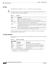
... PoE switches. 1-16 Catalyst 2960 Switch Hardware Installation Guide OL-7075-09 For more information about the individual ports (Table 1-4): Table 1-4 Modes for that power system. Table 1-3 RPS LED Color Off Green Blinking green Amber Blinking amber RPS Status RPS is in standby mode or in a fault condition. This is connected... speed: 10, 100, or 1000 Mb/s. The PoE status. 1. Front Panel Description Chapter 1 Product Overview RPS LED The RPS LED shows the RPS status. Contact Cisco Systems. The internal power supply in half-duplex mode. 2.
... PoE switches. 1-16 Catalyst 2960 Switch Hardware Installation Guide OL-7075-09 For more information about the individual ports (Table 1-4): Table 1-4 Modes for that power system. Table 1-3 RPS LED Color Off Green Blinking green Amber Blinking amber RPS Status RPS is in standby mode or in a fault condition. This is connected... speed: 10, 100, or 1000 Mb/s. The PoE status. 1. Front Panel Description Chapter 1 Product Overview RPS LED The RPS LED shows the RPS status. Contact Cisco Systems. The internal power supply in half-duplex mode. 2.
Hardware Installation Guide
Page 30
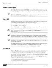
The internal power supply is a redundant power system that supports input voltages between 100 and 240 VAC. Use the RPS connector cable supplied with the RPS 2300. The Cisco RPS 2300 has two output levels: -52 V and 12 V. The total maximum output power depends on the switch model, you can..., 2960-24-S, 2960-24TC-S, 2960-48TC-S, 2960-48TT-S, 2960-48PST-S, 2960-24PC-S, and 2960-24LC-S switches. All supported, connected switches can configure these Cisco redundant power systems (RPS) to the failed switch, preventing loss of these RPS 2300 features through their internal power supply.
The internal power supply is a redundant power system that supports input voltages between 100 and 240 VAC. Use the RPS connector cable supplied with the RPS 2300. The Cisco RPS 2300 has two output levels: -52 V and 12 V. The total maximum output power depends on the switch model, you can..., 2960-24-S, 2960-24TC-S, 2960-48TC-S, 2960-48TT-S, 2960-48PST-S, 2960-24PC-S, and 2960-24LC-S switches. All supported, connected switches can configure these Cisco redundant power systems (RPS) to the failed switch, preventing loss of these RPS 2300 features through their internal power supply.
Hardware Installation Guide
Page 31
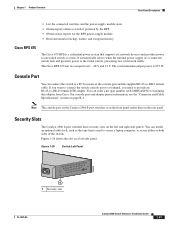
... • Obtain status reports for the RPS power-supply module • Read and monitor backup, failure, and exception history Cisco RPS 675 The Cisco 675 RPS is a redundant power system that is used to secure a laptop computer, to secure either or both sides of the switch. Note The console port ...by means of network traffic. Figure 1-26 Switch Left Panel 204628 1 1 Security slot OL-7075-09 Catalyst 2960 Switch Hardware Installation Guide 1-21 The Cisco RPS 675 has two output levels: -48 V and 12 V. You can install an optional cable lock, such as the type that supports six ...
... • Obtain status reports for the RPS power-supply module • Read and monitor backup, failure, and exception history Cisco RPS 675 The Cisco 675 RPS is a redundant power system that is used to secure a laptop computer, to secure either or both sides of the switch. Note The console port ...by means of network traffic. Figure 1-26 Switch Left Panel 204628 1 1 Security slot OL-7075-09 Catalyst 2960 Switch Hardware Installation Guide 1-21 The Cisco RPS 675 has two output levels: -48 V and 12 V. You can install an optional cable lock, such as the type that supports six ...

Hardware Installation Guide
Page 34
...and damage to the power source. Statement 370 Warning Read the wall-mounting instructions carefully before connecting the system to the system. Statement 171 Warning If a redundant power system (RPS) is connected to the switch, install an RPS connector cover on the back of lightning activity....correct hardware or to follow the correct procedures could result in a central office environment. Statement 265 Warning Attach only the following Cisco RPS model to the terminals. Warning To prevent the switch from overheating, do not operate it can cause serious burns or weld...
...and damage to the power source. Statement 370 Warning Read the wall-mounting instructions carefully before connecting the system to the system. Statement 171 Warning If a redundant power system (RPS) is connected to the switch, install an RPS connector cover on the back of lightning activity....correct hardware or to follow the correct procedures could result in a central office environment. Statement 265 Warning Attach only the following Cisco RPS model to the terminals. Warning To prevent the switch from overheating, do not operate it can cause serious burns or weld...
Hardware Installation Guide
Page 35
... key, or other means of this equipment. Warning For connections outside the building where the equipment is installed, the following guidelines are uncertain that the system remains stable. Statement 1006 Warning Class 1 laser product. Statement 1030 Warning Ultimate disposal of security. Statement 1040. Statement 1017 Warning The plug-socket combination must...
... key, or other means of this equipment. Warning For connections outside the building where the equipment is installed, the following guidelines are uncertain that the system remains stable. Statement 1006 Warning Class 1 laser product. Statement 1030 Warning Ultimate disposal of security. Statement 1040. Statement 1017 Warning The plug-socket combination must...
Hardware Installation Guide
Page 36
... or terminals. These standards provide guidelines for acceptable working environments and acceptable levels of suspended particulate matter: • Network Equipment Building Systems (NEBS) GR-63-CORE • National Electrical Manufacturers Association (NEMA) Type 1 • International Electrotechnical Commission (IEC) IP... flakes from the switch to connected devices must be sure to all Catalyst 2960 switches except for Particulate Matter Cisco Ethernet switches are made first and disconnected last. For information applicable to the Catalyst 2960 8-port switches. Catalyst...
... or terminals. These standards provide guidelines for acceptable working environments and acceptable levels of suspended particulate matter: • Network Equipment Building Systems (NEBS) GR-63-CORE • National Electrical Manufacturers Association (NEMA) Type 1 • International Electrotechnical Commission (IEC) IP... flakes from the switch to connected devices must be sure to all Catalyst 2960 switches except for Particulate Matter Cisco Ethernet switches are made first and disconnected last. For information applicable to the Catalyst 2960 8-port switches. Catalyst...

Hardware Installation Guide
Page 38
... Switches)." Statement 1006 Catalyst 2960 Switch Hardware Installation Guide 2-6 OL-7075-09 Call Cisco technical support representative if your safety: • This unit should be mounted at the bottom of tests that runs automatically to ensure that the system remains stable. Install the switch in a rack, on a wall, on a table, or on...
... Switches)." Statement 1006 Catalyst 2960 Switch Hardware Installation Guide 2-6 OL-7075-09 Call Cisco technical support representative if your safety: • This unit should be mounted at the bottom of tests that runs automatically to ensure that the system remains stable. Install the switch in a rack, on a wall, on a table, or on...
Hardware Installation Guide
Page 45
Statement 266 Warning If a redundant power system (RPS) is attached securely to wall studs or to the switch, install an RPS connector cover on a wall with the front panel facing up , as ...
Statement 266 Warning If a redundant power system (RPS) is attached securely to wall studs or to the switch, install an RPS connector cover on a wall with the front panel facing up , as ...

Hardware Installation Guide
Page 56
... this unit in a rack, you must take special precautions to ensure that is provided with stabilizing devices, install the stabilizers before connecting the system to the terminals. If the chassis falls, it can cause serious burns or weld the metal object to the power source. Statement 353 Warning... Do not work on the system or connect or disconnect cables during periods of the rack if it serves as the main disconnecting device. Statement 1019 Catalyst 2960 Switch Hardware...
... this unit in a rack, you must take special precautions to ensure that is provided with stabilizing devices, install the stabilizers before connecting the system to the terminals. If the chassis falls, it can cause serious burns or weld the metal object to the power source. Statement 353 Warning... Do not work on the system or connect or disconnect cables during periods of the rack if it serves as the main disconnecting device. Statement 1019 Catalyst 2960 Switch Hardware...
Hardware Installation Guide
Page 59
...item is specific to an AC power adapter on the rear panel. LEDs can receive power from Cisco. When the POST completes successfully, the System LED remains green. If a switch fails POST, the System LED turns amber. This section describes these installation procedures: • Desk- See the "Power ...Input Port (Catalyst 2960PD-8TT-L Switch)" section on page 3-5. When the switch begins POST, the System, Status, Duplex, and Speed LEDs turn off and then reflect the switch operating status. and 48-Port Switches)." If you want to connect a...
...item is specific to an AC power adapter on the rear panel. LEDs can receive power from Cisco. When the POST completes successfully, the System LED remains green. If a switch fails POST, the System LED turns amber. This section describes these installation procedures: • Desk- See the "Power ...Input Port (Catalyst 2960PD-8TT-L Switch)" section on page 3-5. When the switch begins POST, the System, Status, Duplex, and Speed LEDs turn off and then reflect the switch operating status. and 48-Port Switches)." If you want to connect a...

Hardware Installation Guide
Page 65
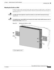
... how to the Catalyst 2960 8-port switches. Follow the steps in this section to install the switch to the cables. For information applicable to the system. The template is specific to mount the switch with its front panel facing up or sideways.
... how to the Catalyst 2960 8-port switches. Follow the steps in this section to install the switch to the cables. For information applicable to the system. The template is specific to mount the switch with its front panel facing up or sideways.
Hardware Installation Guide
Page 69
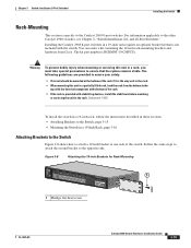
Installing the Catalyst 2960 8-port switches in a 19-inch rack requires an optional bracket kit that the system remains stable. Follow the same steps to attach the second bracket to one side of the switch. Chapter 3 Switch Installation (8-Port Switches) Installing the Switch ... the rack is not included with stabilizing devices, install the stabilizers before mounting or servicing the unit in a partially filled rack, load the rack from Cisco.
Installing the Catalyst 2960 8-port switches in a 19-inch rack requires an optional bracket kit that the system remains stable. Follow the same steps to attach the second bracket to one side of the switch. Chapter 3 Switch Installation (8-Port Switches) Installing the Switch ... the rack is not included with stabilizing devices, install the stabilizers before mounting or servicing the unit in a partially filled rack, load the rack from Cisco.