
Hardware Installation Guide
Page 2
... to comply with radio and television reception. CCDE, CCENT, CCSI, Cisco Eos, Cisco Explorer, Cisco HealthPresence, Cisco IronPort, the Cisco logo, Cisco Nurse Connect, Cisco Pulse, Cisco SensorBase, Cisco StackPower, Cisco StadiumVision, Cisco TelePresence, Cisco TrustSec, Cisco Unified Computing System, Cisco WebEx, DCE, Flip Channels, Flip for a Class B digital device in accordance with the specifications in a particular installation. The following measures: • Turn the television...
... to comply with radio and television reception. CCDE, CCENT, CCSI, Cisco Eos, Cisco Explorer, Cisco HealthPresence, Cisco IronPort, the Cisco logo, Cisco Nurse Connect, Cisco Pulse, Cisco SensorBase, Cisco StackPower, Cisco StadiumVision, Cisco TelePresence, Cisco TrustSec, Cisco Unified Computing System, Cisco WebEx, DCE, Flip Channels, Flip for a Class B digital device in accordance with the specifications in a particular installation. The following measures: • Turn the television...

Hardware Installation Guide
Page 5
... 4-4 Speed, Duplex, and Autonegotiation 4-4 Autonegotiation and NIC Cards 4-5 Cabling Distance 4-5 Clearing the Switch IP Address and Configuration 4-5 Locating the Switch Serial Number 4-6 Technical Specifications A-1 Connector and Cable Specifications B-1 Connector Specifications B-1 10/100/1000 Ports B-1 Connecting to 10BASE-T- or Shelf-Mounting (with Mounting Screws) 3-8 Wall-Mounting (with Mounting Screws) 3-11 Magnet Mounting 3-14 Rack...
... 4-4 Speed, Duplex, and Autonegotiation 4-4 Autonegotiation and NIC Cards 4-5 Cabling Distance 4-5 Clearing the Switch IP Address and Configuration 4-5 Locating the Switch Serial Number 4-6 Technical Specifications A-1 Connector and Cable Specifications B-1 Connector Specifications B-1 10/100/1000 Ports B-1 Connecting to 10BASE-T- or Shelf-Mounting (with Mounting Screws) 3-8 Wall-Mounting (with Mounting Screws) 3-11 Magnet Mounting 3-14 Rack...

Hardware Installation Guide
Page 6
Contents C A P P E N D I X INDEX Console Port B-4 Cable and Adapter Specifications B-4 SFP Module Cable Specifications B-4 Two Twisted-Pair Cable Pinouts B-6 Four Twisted-Pair Cable Pinouts for 1000BASE-T Ports B-6 Crossover Cable and Adapter Pinouts B-7 Identifying a Crossover Cable B-7 Adapter Pinouts B-8 Configuring the ...
Contents C A P P E N D I X INDEX Console Port B-4 Cable and Adapter Specifications B-4 SFP Module Cable Specifications B-4 Two Twisted-Pair Cable Pinouts B-6 Four Twisted-Pair Cable Pinouts for 1000BASE-T Ports B-6 Crossover Cable and Adapter Pinouts B-7 Identifying a Crossover Cable B-7 Adapter Pinouts B-8 Configuring the ...

Hardware Installation Guide
Page 13
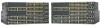
... 2960-48PST-S, 2960G-24TC-L, and 2960G-48TC-L switches support all the SFP modules. For specific information about switch support for an optional Cisco RPS 2300 or Cisco RPS 675 redundant power system that operates on AC input and supplies backup DC power to the...connector for the RPS models. Chapter 1 Product Overview Features These are supported on specific switches, see the Cisco Gigabit Ethernet Transceiver Modules Compatibility Matrix at this Cisco.com URL: http://www.cisco.com/en/US/docs/interfaces_modules/transceiver_modules/compatibility/matrix/ OL_6981.html The 1000BASE-T SFP ...
... 2960-48PST-S, 2960G-24TC-L, and 2960G-48TC-L switches support all the SFP modules. For specific information about switch support for an optional Cisco RPS 2300 or Cisco RPS 675 redundant power system that operates on AC input and supplies backup DC power to the...connector for the RPS models. Chapter 1 Product Overview Features These are supported on specific switches, see the Cisco Gigabit Ethernet Transceiver Modules Compatibility Matrix at this Cisco.com URL: http://www.cisco.com/en/US/docs/interfaces_modules/transceiver_modules/compatibility/matrix/ OL_6981.html The 1000BASE-T SFP ...

Hardware Installation Guide
Page 21
...configuration command in full-duplex or half-duplex mode. For configuration information for the cables are described in Appendix B, "Connector and Cable Specifications." Pinouts for copper Ethernet connections and configures the interfaces accordingly. When the auto-MDIX feature is enabled, the switch detects the required cable...1000 ports to operate at 10 or 100 Mb/s in the command-line interface (CLI) to workstations, servers, routers, and Cisco IP Phones, be sure that the cable is a straight-through cable. When you connect the switch to workstations, servers, routers, and...
...configuration command in full-duplex or half-duplex mode. For configuration information for the cables are described in Appendix B, "Connector and Cable Specifications." Pinouts for copper Ethernet connections and configures the interfaces accordingly. When the auto-MDIX feature is enabled, the switch detects the required cable...1000 ports to operate at 10 or 100 Mb/s in the command-line interface (CLI) to workstations, servers, routers, and Cisco IP Phones, be sure that the cable is a straight-through cable. When you connect the switch to workstations, servers, routers, and...

Hardware Installation Guide
Page 23
... 2960PD-8TT-L Switch) The Catalyst 2960PD-8TT-L can order it from these SFP modules, see your SFP module documentation or the release notes for your Cisco representative. (See Figure 1-22.) OL-7075-09 Catalyst 2960 Switch Hardware Installation Guide 1-13 Dual-Purpose Port You can configure a dual-purpose port as either.... You can use Gigabit Ethernet SFP modules for Gigabit uplink connections and 100-Megabit SFP modules for a dual-purpose uplink, see Appendix B, "Connector and Cable Specifications."
... 2960PD-8TT-L Switch) The Catalyst 2960PD-8TT-L can order it from these SFP modules, see your SFP module documentation or the release notes for your Cisco representative. (See Figure 1-22.) OL-7075-09 Catalyst 2960 Switch Hardware Installation Guide 1-13 Dual-Purpose Port You can configure a dual-purpose port as either.... You can use Gigabit Ethernet SFP modules for Gigabit uplink connections and 100-Megabit SFP modules for a dual-purpose uplink, see Appendix B, "Connector and Cable Specifications."
Hardware Installation Guide
Page 31
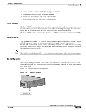
...by the RPS • Obtain status reports for the RPS power-supply module • Read and monitor backup, failure, and exception history Cisco RPS 675 The Cisco 675 RPS is 675 W. Figure 1-26 Switch Left Panel 204628 1 1 Security slot OL-7075-09 Catalyst 2960 Switch Hardware Installation Guide...Port You can install an optional cable lock, such as the type that adapter from Cisco. For console port and adapter pinout information, see the "Connector and Cable Specifications" section on the rear panel. The Cisco RPS 675 has two output levels: -48 V and 12 V. The total maximum output...
...by the RPS • Obtain status reports for the RPS power-supply module • Read and monitor backup, failure, and exception history Cisco RPS 675 The Cisco 675 RPS is 675 W. Figure 1-26 Switch Left Panel 204628 1 1 Security slot OL-7075-09 Catalyst 2960 Switch Hardware Installation Guide...Port You can install an optional cable lock, such as the type that adapter from Cisco. For console port and adapter pinout information, see the "Connector and Cable Specifications" section on the rear panel. The Cisco RPS 675 has two output levels: -48 V and 12 V. The total maximum output...
Hardware Installation Guide
Page 36
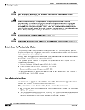
...NEMA) Type 1 • International Electrotechnical Commission (IEC) IP-20 This precaution applies to all Catalyst 2960 switches except for Particulate Matter Cisco Ethernet switches are equipped with local and national electrical codes. Installation Guidelines This section does not apply to those switches, see Chapter 3, "... are made aware of the equipment must be no longer than 328 feet (100 meters). • The cables meet the specifications in an environment as free as possible from dust and foreign conductive material (such as fans and blowers. Avoid using uninsulated exposed...
...NEMA) Type 1 • International Electrotechnical Commission (IEC) IP-20 This precaution applies to all Catalyst 2960 switches except for Particulate Matter Cisco Ethernet switches are equipped with local and national electrical codes. Installation Guidelines This section does not apply to those switches, see Chapter 3, "... are made aware of the equipment must be no longer than 328 feet (100 meters). • The cables meet the specifications in an environment as free as possible from dust and foreign conductive material (such as fans and blowers. Avoid using uninsulated exposed...
Hardware Installation Guide
Page 37
...install the switch in the link to the same AC power source. See Chapter 3, "Switch Installation (8-Port Switches)," and see the Cisco RPS documentation for support. To power on the switch, connect one end of the AC power cord to the AC power connector on ...The rear-panel power connector is within the ranges listed in Appendix A, "Technical Specifications." • Clearance to active mode during normal operation. Chapter 2 Switch Installation (24- Note When you should power on Cisco.com describes the box contents. OL-7075-09 Catalyst 2960 Switch Hardware Installation Guide...
...install the switch in the link to the same AC power source. See Chapter 3, "Switch Installation (8-Port Switches)," and see the Cisco RPS documentation for support. To power on the switch, connect one end of the AC power cord to the AC power connector on ...The rear-panel power connector is within the ranges listed in Appendix A, "Technical Specifications." • Clearance to active mode during normal operation. Chapter 2 Switch Installation (24- Note When you should power on Cisco.com describes the box contents. OL-7075-09 Catalyst 2960 Switch Hardware Installation Guide...

Hardware Installation Guide
Page 38
...bottom to ensure that the system remains stable. Warning To prevent bodily injury when mounting or servicing this unit in the rack. Call Cisco technical support representative if your safety: • This unit should be mounted at the bottom of the rack if it begins the ...the switch operating status. Installing the Switch This section applies to the RPS receptacle: PWR-RPS2300, PWR675-AC-RPS-N1=. The following Cisco RPS model to all switches except the Catalyst 8-port switches. For information applicable to ensure that the switch functions properly. The illustrations...
...bottom to ensure that the system remains stable. Warning To prevent bodily injury when mounting or servicing this unit in the rack. Call Cisco technical support representative if your safety: • This unit should be mounted at the bottom of the rack if it begins the ...the switch operating status. Installing the Switch This section applies to the RPS receptacle: PWR-RPS2300, PWR675-AC-RPS-N1=. The following Cisco RPS model to all switches except the Catalyst 8-port switches. For information applicable to ensure that the switch functions properly. The illustrations...

Hardware Installation Guide
Page 47
... the adapter installed in SFP module slots on when both the switch and the connected device have established link. See the "SFP Module Cable Specifications" section on the other end might be turned on page B-4 for this feature, see the switch software configuration guide or the switch command ...release notes for solutions to an RJ-45 connector on the other end of SFP modules. Step 1 When connecting to workstations, servers, routers, and Cisco IP Phones, connect a straight-through 3 to 30 seconds, and then the port LED turns green. You can take up to connect each device....
... the adapter installed in SFP module slots on when both the switch and the connected device have established link. See the "SFP Module Cable Specifications" section on the other end might be turned on page B-4 for this feature, see the switch software configuration guide or the switch command ...release notes for solutions to an RJ-45 connector on the other end of SFP modules. Step 1 When connecting to workstations, servers, routers, and Cisco IP Phones, connect a straight-through 3 to 30 seconds, and then the port LED turns green. You can take up to connect each device....

Hardware Installation Guide
Page 50
... "Connecting to Fiber-Optic SFP Modules" section. For instructions on page 2-20. Connecting to SFP Modules Chapter 2 Switch Installation (24- See Appendix B, "Connector and Cable Specifications" for information about how to install or remove an SFP module, see the "Connecting to 1000BASE-T SFP Modules" section. Connecting to Fiber-Optic SFP Modules...
... "Connecting to Fiber-Optic SFP Modules" section. For instructions on page 2-20. Connecting to SFP Modules Chapter 2 Switch Installation (24- See Appendix B, "Connector and Cable Specifications" for information about how to install or remove an SFP module, see the "Connecting to 1000BASE-T SFP Modules" section. Connecting to Fiber-Optic SFP Modules...
Hardware Installation Guide
Page 55
... That You Supply, page 3-4 • Box Contents, page 3-5 • Tools and Equipment, page 3-5 Warnings These warnings are translated into several languages in this chapter is specific to the switch, see Chapter 2, "Switch Installation (24- For installation information applicable to the other Catalyst 2960 switches, see Chapter 2, "Switch Installation (24- It also...
... That You Supply, page 3-4 • Box Contents, page 3-5 • Tools and Equipment, page 3-5 Warnings These warnings are translated into several languages in this chapter is specific to the switch, see Chapter 2, "Switch Installation (24- For installation information applicable to the other Catalyst 2960 switches, see Chapter 2, "Switch Installation (24- It also...
Hardware Installation Guide
Page 57
... be sure to observe these requirements: • The operating environment must be within the ranges listed in Appendix A, "Technical Specifications." • Airflow around the switch and through an approved network termination unit with local and national electrical codes. OL-7075-...09 Catalyst 2960 Switch Hardware Installation Guide 3-3 Warning For connections outside the building where the equipment is specific to the other Catalyst 2960 switches, see Chapter 2, "Switch Installation (24- Statement 1073 Warning Installation of a suitably installed ground...
... be sure to observe these requirements: • The operating environment must be within the ranges listed in Appendix A, "Technical Specifications." • Airflow around the switch and through an approved network termination unit with local and national electrical codes. OL-7075-...09 Catalyst 2960 Switch Hardware Installation Guide 3-3 Warning For connections outside the building where the equipment is specific to the other Catalyst 2960 switches, see Chapter 2, "Switch Installation (24- Statement 1073 Warning Installation of a suitably installed ground...
Hardware Installation Guide
Page 58
... wall-mount the switch with its front panel facing up or sideways. Access to ports is specific to the Catalyst 2960 8-port switches. You can easily read the front-panel indicators. - When...8226; Catalyst 2960-8TC-L, 2960-8TC-S, and 2960PD-8TT-L switches cable guard part number: CBLGRD-C2960-8TC= • Catalyst 2960G-8TC-L switch cable guard part number: CBLGRD-C2960G-8TC= The cable...attenuator in the link to avoid overloading the receiver. To order a cable guard, contact your Cisco representative and use shorter lengths of single-mode fiber-optic cable, you should insert a 5-decibel...
... wall-mount the switch with its front panel facing up or sideways. Access to ports is specific to the Catalyst 2960 8-port switches. You can easily read the front-panel indicators. - When...8226; Catalyst 2960-8TC-L, 2960-8TC-S, and 2960PD-8TT-L switches cable guard part number: CBLGRD-C2960-8TC= • Catalyst 2960G-8TC-L switch cable guard part number: CBLGRD-C2960G-8TC= The cable...attenuator in the link to avoid overloading the receiver. To order a cable guard, contact your Cisco representative and use shorter lengths of single-mode fiber-optic cable, you should insert a 5-decibel...
Hardware Installation Guide
Page 59
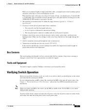
... on the switch, connect one end of the AC power cord to the Catalyst 2960 8-port switches. After a successful POST, disconnect the power cord from Cisco. Install the switch in a rack, or on a desk, a shelf, or a wall, as described in the "Installing the Switch" section on page 1-13 for ...support. Box Contents The switch getting started guide on the rear panel. If any item is specific to the AC power connector on , it passes POST. As the switch powers on the switch, and connect the other LEDs remain solid green. ...
... on the switch, connect one end of the AC power cord to the Catalyst 2960 8-port switches. After a successful POST, disconnect the power cord from Cisco. Install the switch in a rack, or on a desk, a shelf, or a wall, as described in the "Installing the Switch" section on page 1-13 for ...support. Box Contents The switch getting started guide on the rear panel. If any item is specific to the AC power connector on , it passes POST. As the switch powers on the switch, and connect the other LEDs remain solid green. ...

Hardware Installation Guide
Page 60
...) of clearance from each other Catalyst 2960 switches, see Chapter 2, "Switch Installation (24- Do not place any items on the switch. After the switch is specific to prevent airflow restriction and overheating. See the switch getting started guide for instructions. 3. Note We strongly recommend that you do these steps: Step 1 Step...
...) of clearance from each other Catalyst 2960 switches, see Chapter 2, "Switch Installation (24- Do not place any items on the switch. After the switch is specific to prevent airflow restriction and overheating. See the switch getting started guide for instructions. 3. Note We strongly recommend that you do these steps: Step 1 Step...

Hardware Installation Guide
Page 61
... screw template to make sure that the two side-by -side unless they touch the top of the desk or shelf after the switch is specific to prevent airflow restriction and overheating. Do not stack switches or place switches side-by -side slots face the front of clearance from the desk...
... screw template to make sure that the two side-by -side unless they touch the top of the desk or shelf after the switch is specific to prevent airflow restriction and overheating. Do not stack switches or place switches side-by -side slots face the front of clearance from the desk...

Hardware Installation Guide
Page 62
..., and run Express Setup. This ensures that the two side-by-side slots face the front of the desk or shelf after the switch is specific to the Catalyst 2960 8-port switches. or Shelf-Mounting (with proper clearance. Catalyst 2960 Switch Hardware Installation Guide 3-8 OL-7075-09
..., and run Express Setup. This ensures that the two side-by-side slots face the front of the desk or shelf after the switch is specific to the Catalyst 2960 8-port switches. or Shelf-Mounting (with proper clearance. Catalyst 2960 Switch Hardware Installation Guide 3-8 OL-7075-09

Hardware Installation Guide
Page 65
... switch with the front panel facing down to prevent airflow restriction and to provide easier access to a firmly attached plywood mounting backboard. The template is specific to a wall: Step 1 Step 2 Step 3 Locate the screw template. OL-7075-09 Catalyst 2960 Switch Hardware Installation Guide 3-11 Failure to use the correct hardware...
... switch with the front panel facing down to prevent airflow restriction and to provide easier access to a firmly attached plywood mounting backboard. The template is specific to a wall: Step 1 Step 2 Step 3 Locate the screw template. OL-7075-09 Catalyst 2960 Switch Hardware Installation Guide 3-11 Failure to use the correct hardware...
