Hardware Installation Guide
Page 3
... LEDs and Modes 1-16 Dual-Purpose Port LEDs 1-18 Cable Guard for the Catalyst 2960 8-Port Switches 1-19 Rear Panel Description 1-19 Internal Power Supply 1-20 Cisco RPS 1-20 Cisco RPS 2300 1-20 Cisco RPS 675 1-21 Console Port 1-21 Security Slots 1-21 Management Options 1-22 Network Configurations 1-22 Catalyst 2960 Switch Hardware Installation...
... LEDs and Modes 1-16 Dual-Purpose Port LEDs 1-18 Cable Guard for the Catalyst 2960 8-Port Switches 1-19 Rear Panel Description 1-19 Internal Power Supply 1-20 Cisco RPS 1-20 Cisco RPS 2300 1-20 Cisco RPS 675 1-21 Console Port 1-21 Security Slots 1-21 Management Options 1-22 Network Configurations 1-22 Catalyst 2960 Switch Hardware Installation...

Hardware Installation Guide
Page 11
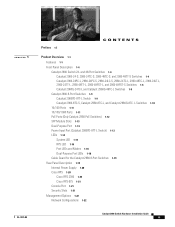
...Cisco IP Phones, and other network devices including servers, routers, and other network devices. Table 1-1 describes the switch model features. and 48-port Catalyst 2960 switches as backbone switches, aggregating 10BASE-T, 100BASE-TX, and 1000BASE-T Ethernet traffic from other switches. Table 1-1 Catalyst 2960 Switch Model Descriptions... the Catalyst 2960 switch. These topics are included: • Features, page 1-1 • Front Panel Description, page 1-4 • Rear Panel Description, page 1-19 • Management Options, page 1-22 Features You can deploy the 24- This chapter...
...Cisco IP Phones, and other network devices including servers, routers, and other network devices. Table 1-1 describes the switch model features. and 48-port Catalyst 2960 switches as backbone switches, aggregating 10BASE-T, 100BASE-TX, and 1000BASE-T Ethernet traffic from other switches. Table 1-1 Catalyst 2960 Switch Model Descriptions... the Catalyst 2960 switch. These topics are included: • Features, page 1-1 • Front Panel Description, page 1-4 • Rear Panel Description, page 1-19 • Management Options, page 1-22 Features You can deploy the 24- This chapter...
Hardware Installation Guide
Page 12
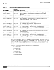
...-L Catalyst 2960G-24TC-L Catalyst 2960-24TT-L Catalyst 2960-48PST-L Catalyst 2960-48TC-L Catalyst 2960G-48TC-L Catalyst 2960-48TT-L Supported Software Image Description LAN-Lite 24 10/100BASE-TX ports (8 of which are PoE) and 2 dual-purpose ports LAN-Base 8 10/100BASE-TX Ethernet ports...the installation instructions for more information. See "Catalyst 2960 8-Port Switches" section on page 1-9 for these switch models. They can be mounted with Cisco prestandard PoE and IEEE 802.3af: • Catalyst 2960-24LC-S • Catalyst 2960-24LT-L • Catalyst 2960-24PC-L • Catalyst 2960...
...-L Catalyst 2960G-24TC-L Catalyst 2960-24TT-L Catalyst 2960-48PST-L Catalyst 2960-48TC-L Catalyst 2960G-48TC-L Catalyst 2960-48TT-L Supported Software Image Description LAN-Lite 24 10/100BASE-TX ports (8 of which are PoE) and 2 dual-purpose ports LAN-Base 8 10/100BASE-TX Ethernet ports...the installation instructions for more information. See "Catalyst 2960 8-Port Switches" section on page 1-9 for these switch models. They can be mounted with Cisco prestandard PoE and IEEE 802.3af: • Catalyst 2960-24LC-S • Catalyst 2960-24LT-L • Catalyst 2960-24PC-L • Catalyst 2960...

Hardware Installation Guide
Page 14
... the Catalyst 2960 24- These switches have dual-purpose ports, that port, but not Catalyst 2960 Switch Hardware Installation Guide 1-4 OL-7075-09 Front Panel Description Chapter 1 Product Overview Front Panel Description These sections describe the switch front panels: • Catalyst 2960 Switch 24-
... the Catalyst 2960 24- These switches have dual-purpose ports, that port, but not Catalyst 2960 Switch Hardware Installation Guide 1-4 OL-7075-09 Front Panel Description Chapter 1 Product Overview Front Panel Description These sections describe the switch front panels: • Catalyst 2960 Switch 24-

Hardware Installation Guide
Page 15
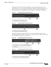
... the "Dual-Purpose Port" section on . This switch has two 10/100/1000 uplink ports, numbered 1 and 2. The See Figure 1-4. Chapter 1 Product Overview Front Panel Description both at the same time.
... the "Dual-Purpose Port" section on . This switch has two 10/100/1000 uplink ports, numbered 1 and 2. The See Figure 1-4. Chapter 1 Product Overview Front Panel Description both at the same time.

Hardware Installation Guide
Page 16
...-S Switch Front Panel 206730 1 2 3 1 10/100 PoE ports 3 Dual-purpose ports 2 10/100 ports Catalyst 2960 Switch Hardware Installation Guide 1-6 OL-7075-09 Front Panel Description Chapter 1 Product Overview Catalyst 2960-24PC-L, 2960-24PC-S, 2960-24LC-S, 2960-24TC-L, 2960-48TC-L, 2960-24LT-L, 2960-24TT-L, 2960-48TT-L, 2960-48PST-L, and 2960-48PST...
...-S Switch Front Panel 206730 1 2 3 1 10/100 PoE ports 3 Dual-purpose ports 2 10/100 ports Catalyst 2960 Switch Hardware Installation Guide 1-6 OL-7075-09 Front Panel Description Chapter 1 Product Overview Catalyst 2960-24PC-L, 2960-24PC-S, 2960-24LC-S, 2960-24TC-L, 2960-48TC-L, 2960-24LT-L, 2960-24TT-L, 2960-48TT-L, 2960-48PST-L, and 2960-48PST...
Hardware Installation Guide
Page 17
... is, 10/100/1000 ports 1 and 2 can use either the SFP module or the RJ-45 connector for these ports. Chapter 1 Product Overview Front Panel Description The Catalyst 2960-24TC-L and Catalyst 2960-48TC-L switches have two 10/100/1000 uplink ports, numbered 1 and 2.
... is, 10/100/1000 ports 1 and 2 can use either the SFP module or the RJ-45 connector for these ports. Chapter 1 Product Overview Front Panel Description The Catalyst 2960-24TC-L and Catalyst 2960-48TC-L switches have two 10/100/1000 uplink ports, numbered 1 and 2.

Hardware Installation Guide
Page 18
... type for that port, but not both. Ports 1 to 48 on the Catalyst 2960G-48TC-L switch. The SFP module slots are PoE ports. Front Panel Description Chapter 1 Product Overview Figure 1-12 Catalyst 2960-48TT-L Switch Front Panel 204609 SYST RPS STAT DUPLX SPEED MODE 1 2 1 10/100 ports 2 10/100/1000 uplink...
... type for that port, but not both. Ports 1 to 48 on the Catalyst 2960G-48TC-L switch. The SFP module slots are PoE ports. Front Panel Description Chapter 1 Product Overview Figure 1-12 Catalyst 2960-48TT-L Switch Front Panel 204609 SYST RPS STAT DUPLX SPEED MODE 1 2 1 10/100 ports 2 10/100/1000 uplink...

Hardware Installation Guide
Page 19
Chapter 1 Product Overview Front Panel Description Figure 1-15 Catalyst 2960G-24TC-L Switch Front Panel 204610 SYST RPS STAT DUPLX SPEED MODE 1 2 1 10/100/1000 ports 2 Dual-purpose ports Figure 1-16 Catalyst ...
Chapter 1 Product Overview Front Panel Description Figure 1-15 Catalyst 2960G-24TC-L Switch Front Panel 204610 SYST RPS STAT DUPLX SPEED MODE 1 2 1 10/100/1000 ports 2 Dual-purpose ports Figure 1-16 Catalyst ...

Hardware Installation Guide
Page 20
... Catalyst 2960G Series 1 204633 1 2 3 1 Console port 3 Dual-purpose port 2 10/100/1000 ports 1-10 Catalyst 2960 Switch Hardware Installation Guide OL-7075-09 Front Panel Description Chapter 1 Product Overview Catalyst 2960-8TC-S, Catalyst 2960-8TC-L, and Catalyst 2960G-8TC -L Switches The console ports for the Catalyst 2960-8TC-S, Catalyst 2960-8TC...
... Catalyst 2960G Series 1 204633 1 2 3 1 Console port 3 Dual-purpose port 2 10/100/1000 ports 1-10 Catalyst 2960 Switch Hardware Installation Guide OL-7075-09 Front Panel Description Chapter 1 Product Overview Catalyst 2960-8TC-S, Catalyst 2960-8TC-L, and Catalyst 2960G-8TC -L Switches The console ports for the Catalyst 2960-8TC-S, Catalyst 2960-8TC...

Hardware Installation Guide
Page 21
...is a straight-through cable for copper Ethernet connections and configures the interfaces accordingly. When you connect the switch to workstations, servers, routers, and Cisco IP Phones, be within 328 feet (100 meters). 100BASE-TX traffic requires a Category 5 or higher cable. 10BASE-T traffic can use Category 3...-pair, Category 5 or higher cable for speed and duplex autonegotiation. (The default setting is autonegotiate. Chapter 1 Product Overview Front Panel Description 10/100 Ports You can set the 10/100 ports to switches or hubs, use a crossover cable. You can also set these ...
...is a straight-through cable for copper Ethernet connections and configures the interfaces accordingly. When you connect the switch to workstations, servers, routers, and Cisco IP Phones, be within 328 feet (100 meters). 100BASE-TX traffic requires a Category 5 or higher cable. 10BASE-T traffic can use Category 3...-pair, Category 5 or higher cable for speed and duplex autonegotiation. (The default setting is autonegotiate. Chapter 1 Product Overview Front Panel Description 10/100 Ports You can set the 10/100 ports to switches or hubs, use a crossover cable. You can also set these ...
Hardware Installation Guide
Page 22
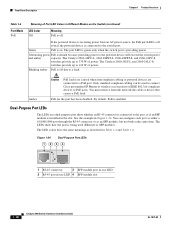
Front Panel Description Chapter 1 Product Overview PoE Ports (Only Catalyst 2960 PoE Switches) This...power source as an IEEE 802.3af-compliant powered device, a Cisco prestandard IP phone, or a Cisco prestandard Cisco access point, is connected. For information about Cisco IP Phones and Cisco Aironet Access Points, see the switch software configuration guide. Warning ...Voltages that case, the PoE port becomes the backup power source for each 10/100 PoE port: - The Cisco prestandard PoE is connected. • You also can control whether or not a Catalyst 2960 PoE port automatically ...
Front Panel Description Chapter 1 Product Overview PoE Ports (Only Catalyst 2960 PoE Switches) This...power source as an IEEE 802.3af-compliant powered device, a Cisco prestandard IP phone, or a Cisco prestandard Cisco access point, is connected. For information about Cisco IP Phones and Cisco Aironet Access Points, see the switch software configuration guide. Warning ...Voltages that case, the PoE port becomes the backup power source for each 10/100 PoE port: - The Cisco prestandard PoE is connected. • You also can control whether or not a Catalyst 2960 PoE port automatically ...

Hardware Installation Guide
Page 23
... as an SFP module port. You use Gigabit Ethernet SFP modules for Gigabit uplink connections and 100-Megabit SFP modules for your Cisco representative. (See Figure 1-22.) OL-7075-09 Catalyst 2960 Switch Hardware Installation Guide 1-13 The switch activates only one shows... the switch, but you can receive power from these SFP modules, see the software configuration guide. Chapter 1 Product Overview Front Panel Description SFP Module Slots The Catalyst 2960 switches (other switches. For more information about configuring speed and duplex settings for a dual-purpose uplink...
... as an SFP module port. You use Gigabit Ethernet SFP modules for Gigabit uplink connections and 100-Megabit SFP modules for your Cisco representative. (See Figure 1-22.) OL-7075-09 Catalyst 2960 Switch Hardware Installation Guide 1-13 The switch activates only one shows... the switch, but you can receive power from these SFP modules, see the software configuration guide. Chapter 1 Product Overview Front Panel Description SFP Module Slots The Catalyst 2960 switches (other switches. For more information about configuring speed and duplex settings for a dual-purpose uplink...
Hardware Installation Guide
Page 24
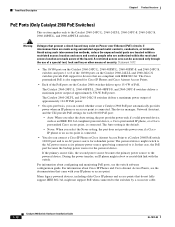
... a single switch. The switch software configuration guide describes how to use the CLI to configure and to monitor switch activity and its performance. Front Panel Description Chapter 1 Product Overview Figure 1-21 Connecting Through a 10/100/1000 Port SYST STAT DPLX SPD 1x 2x 3x 4x 5x 6x 7x 8x CONSOLE MODE...
... a single switch. The switch software configuration guide describes how to use the CLI to configure and to monitor switch activity and its performance. Front Panel Description Chapter 1 Product Overview Figure 1-21 Connecting Through a 10/100/1000 Port SYST STAT DPLX SPD 1x 2x 3x 4x 5x 6x 7x 8x CONSOLE MODE...

Hardware Installation Guide
Page 25
.... Table 1-2 System LED Color Off Green Amber System Status System is not functioning properly. Chapter 1 Product Overview Figure 1-23 Catalyst 2960 Switch LEDs 8 Front Panel Description System LED 204612 1 2 3 4 5 6 SYST RPS STAT DUPLX SPEED PoE MODE 7 12 1X 34 56 78 9 10 11 12 11X 1 SYST LED 5 Speed LED 2 RPS LED...
.... Table 1-2 System LED Color Off Green Amber System Status System is not functioning properly. Chapter 1 Product Overview Figure 1-23 Catalyst 2960 Switch LEDs 8 Front Panel Description System LED 204612 1 2 3 4 5 6 SYST RPS STAT DUPLX SPEED PoE MODE 7 12 1X 34 56 78 9 10 11 12 11X 1 SYST LED 5 Speed LED 2 RPS LED...
Hardware Installation Guide
Page 26
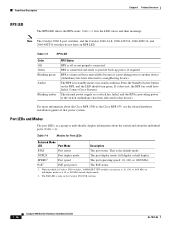
RPS is connected but is providing power to the switch (redundancy has been allocated to a neighboring device). Contact Cisco Systems. The internal power supply in a switch has failed, and the RPS is unavailable because it does not, the RPS fan could have ...group or individually, display information about the switch and about the Cisco RPS 2300 or the Cisco RPS 675, see the related hardware installation guide for Port LEDs Selected Mode LED Port Mode Description STAT Port status The port status. Front Panel Description Chapter 1 Product Overview RPS LED The RPS LED shows the ...
RPS is connected but is providing power to the switch (redundancy has been allocated to a neighboring device). Contact Cisco Systems. The internal power supply in a switch has failed, and the RPS is unavailable because it does not, the RPS fan could have ...group or individually, display information about the switch and about the Cisco RPS 2300 or the Cisco RPS 675, see the related hardware installation guide for Port LEDs Selected Mode LED Port Mode Description STAT Port status The port status. Front Panel Description Chapter 1 Product Overview RPS LED The RPS LED shows the ...

Hardware Installation Guide
Page 27
... of the port LED colors also change a mode, press the Mode button until the desired mode is not forwarding data. Chapter 1 Product Overview Front Panel Description Even if the PoE mode is not selected, the PoE LED shows PoE problems when they are in a fault condition. At least one of Port...
... of the port LED colors also change a mode, press the Mode button until the desired mode is not forwarding data. Chapter 1 Product Overview Front Panel Description Even if the PoE mode is not selected, the PoE LED shows PoE problems when they are in a fault condition. At least one of Port...
Hardware Installation Guide
Page 28
... fault. By default, PoE is off even if the powered device is being used to connect Cisco prestandard IP Phones or wireless access points or IEEE 802.3af-compliant devices to the switch port. Front Panel Description Chapter 1 Product Overview Table 1-6 Port Mode PoE Meaning of Port LED Colors in Different Modes...
... fault. By default, PoE is off even if the powered device is being used to connect Cisco prestandard IP Phones or wireless access points or IEEE 802.3af-compliant devices to the switch port. Front Panel Description Chapter 1 Product Overview Table 1-6 Port Mode PoE Meaning of Port LED Colors in Different Modes...
Hardware Installation Guide
Page 29
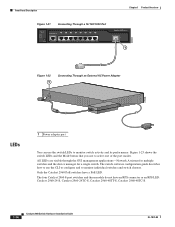
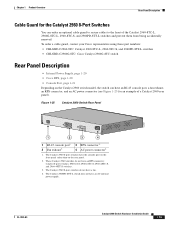
...order a cable guard, contact your Cisco representative using these part numbers: • CBLGRD-C2960-8TC: Catalyst 2960-8TC-L, 2960-8TC-S, and 2960PD-8TT-L switches • CBLGRD-C2960G-8TC: Cisco Catalyst 2960G-8TC switch Rear Panel Description • Internal Power Supply, page 1-20 • Cisco RPS, page 1-20 • ...than on the Catalyst 2960 switch model, the switch can have an AC internal power supply. Chapter 1 Product Overview Rear Panel Description Cable Guard for an example of the Catalyst 2960-8TC-L, 2960G-8TC-L, 2960-8TC-S, and 2960PD-8TT-L switches and prevent ...
...order a cable guard, contact your Cisco representative using these part numbers: • CBLGRD-C2960-8TC: Catalyst 2960-8TC-L, 2960-8TC-S, and 2960PD-8TT-L switches • CBLGRD-C2960G-8TC: Cisco Catalyst 2960G-8TC switch Rear Panel Description • Internal Power Supply, page 1-20 • Cisco RPS, page 1-20 • ...than on the Catalyst 2960 switch model, the switch can have an AC internal power supply. Chapter 1 Product Overview Rear Panel Description Cable Guard for an example of the Catalyst 2960-8TC-L, 2960G-8TC-L, 2960-8TC-S, and 2960PD-8TT-L switches and prevent ...
Hardware Installation Guide
Page 30
...and 2960-24LC-S switches. Use the RPS connector cable supplied with the RPS 2300. Note These Catalyst 2960 switches support only the Cisco RPS 2300: Catalyst 2960-24PC-L, 2960-24LT-L, and 2960-48PST-L switches. The total maximum output power depends on page 1-13. You can....html Cisco RPS 2300 The Cisco RPS 2300 is an autoranging unit that supports six network switches and provides power to the switch. All supported, connected switches can connect the switch to either of these RPS 2300 features through their internal power supply. Rear Panel Description Chapter ...
...and 2960-24LC-S switches. Use the RPS connector cable supplied with the RPS 2300. Note These Catalyst 2960 switches support only the Cisco RPS 2300: Catalyst 2960-24PC-L, 2960-24LT-L, and 2960-48PST-L switches. The total maximum output power depends on page 1-13. You can....html Cisco RPS 2300 The Cisco RPS 2300 is an autoranging unit that supports six network switches and provides power to the switch. All supported, connected switches can connect the switch to either of these RPS 2300 features through their internal power supply. Rear Panel Description Chapter ...