
Hardware Installation Guide
Page 3
... Documentation and Submitting a Service Request i-ix Product Overview 1-1 Setting Up the Switch 1-1 Features 1-1 Front Panel Description 1-3 Fast Ethernet Switch Front Panel Descriptions 1-3 Gigabit Ethernet Switch Front Panel Descriptions 1-6 10/100 and 10/100/1000 Ports 1-8 PoE Ports 1-9 SFP Module Slots 1-10 SFP Modules 1-10...LEDs and Modes 1-13 Dual-Purpose Port LEDs 1-15 Cable Guard 1-15 Rear Panel Description 1-15 Internal Power Supply 1-18 DC Power Connector 1-18 Cisco RPS 1-19 Cisco RPS 2300 1-19 Cisco RPS 675 1-19 Console Port 1-19 Security Slots 1-20 Management Options 1-20 Catalyst ...
... Documentation and Submitting a Service Request i-ix Product Overview 1-1 Setting Up the Switch 1-1 Features 1-1 Front Panel Description 1-3 Fast Ethernet Switch Front Panel Descriptions 1-3 Gigabit Ethernet Switch Front Panel Descriptions 1-6 10/100 and 10/100/1000 Ports 1-8 PoE Ports 1-9 SFP Module Slots 1-10 SFP Modules 1-10...LEDs and Modes 1-13 Dual-Purpose Port LEDs 1-15 Cable Guard 1-15 Rear Panel Description 1-15 Internal Power Supply 1-18 DC Power Connector 1-18 Cisco RPS 1-19 Cisco RPS 2300 1-19 Cisco RPS 675 1-19 Console Port 1-19 Security Slots 1-20 Management Options 1-20 Catalyst ...

Hardware Installation Guide
Page 11
... classrooms. The switches are included: • Setting Up the Switch, page 1-1 • Features, page 1-1 • Front Panel Description, page 1-3 • Rear Panel Description, page 1-15 • Management Options, page 1-20 Setting Up the Switch See the Catalyst 3560 Switch Getting Started Guide for an ...optional Cisco RPS 2300 or Cisco RPS 675 that operates on how to use Express Setup to initially configure your switch ...
... classrooms. The switches are included: • Setting Up the Switch, page 1-1 • Features, page 1-1 • Front Panel Description, page 1-3 • Rear Panel Description, page 1-15 • Management Options, page 1-20 Setting Up the Switch See the Catalyst 3560 Switch Getting Started Guide for an ...optional Cisco RPS 2300 or Cisco RPS 675 that operates on how to use Express Setup to initially configure your switch ...

Hardware Installation Guide
Page 12
Features Chapter 1 Product Overview Table 1-1 Catalyst 3560 Switch Model Descriptions Switch Model Description FastEthernet Catalyst 3560-24PS 24 10/100 Power over Ethernet (PoE) ports and 2 small form-factor pluggable (SFP) module slots Catalyst 3560-24TS-S 24 10/100 ports...and 48-port switches) • 1000BASE-ZX • Coarse Wavelength-Division Multiplexing (CWDM) • SFP module patch cable. (CAB-SFP-50CM=.) Switches running Cisco IOS Release 12.2(25)SEB or later support this patch cable. and 12-port switches) • 1000BASE-BX10 • 1000BASE-LX • 1000BASE-SX &#...
Features Chapter 1 Product Overview Table 1-1 Catalyst 3560 Switch Model Descriptions Switch Model Description FastEthernet Catalyst 3560-24PS 24 10/100 Power over Ethernet (PoE) ports and 2 small form-factor pluggable (SFP) module slots Catalyst 3560-24TS-S 24 10/100 ports...and 48-port switches) • 1000BASE-ZX • Coarse Wavelength-Division Multiplexing (CWDM) • SFP module patch cable. (CAB-SFP-50CM=.) Switches running Cisco IOS Release 12.2(25)SEB or later support this patch cable. and 12-port switches) • 1000BASE-BX10 • 1000BASE-LX • 1000BASE-SX &#...

Hardware Installation Guide
Page 13
..., page 1-10 • Dual-Purpose Port, page 1-10 • LEDs, page 1-11 • Cable Guard, page 1-15 Fast Ethernet Switch Front Panel Descriptions • Catalyst 3560-24PS and 3560V2-24PS Switch Front Panel, Figure 1-1 on page 1-3 • Catalyst 3560-24TS-S, 3560V2-24TS, and 3560V2-24TS-SD Switch Front Panel, Figure 1-2 on page 1-4 •...
..., page 1-10 • Dual-Purpose Port, page 1-10 • LEDs, page 1-11 • Cable Guard, page 1-15 Fast Ethernet Switch Front Panel Descriptions • Catalyst 3560-24PS and 3560V2-24PS Switch Front Panel, Figure 1-1 on page 1-3 • Catalyst 3560-24TS-S, 3560V2-24TS, and 3560V2-24TS-SD Switch Front Panel, Figure 1-2 on page 1-4 •...

Hardware Installation Guide
Page 14
... are numbered 1 to 4. The first member of the pair (port 1) is above the second member (port 2) on the left , as shown in pairs. Front Panel Description Chapter 1 Product Overview The 10/100 ports on the switch are grouped in Figure 1-3. The SFP module slots are numbered 1 and 2. Port 3 is above port...
... are numbered 1 to 4. The first member of the pair (port 1) is above the second member (port 2) on the left , as shown in pairs. Front Panel Description Chapter 1 Product Overview The 10/100 ports on the switch are grouped in Figure 1-3. The SFP module slots are numbered 1 and 2. Port 3 is above port...

Hardware Installation Guide
Page 15
...-purpose port can use either an RJ-45 connector or an SFP module, but not both at the same time. Chapter 1 Product Overview Front Panel Description The 10/100 ports on the switch are numbered 1 to 4. For more information on the dual-purpose port, see the "Console Port" section on . The...
...-purpose port can use either an RJ-45 connector or an SFP module, but not both at the same time. Chapter 1 Product Overview Front Panel Description The 10/100 ports on the switch are numbered 1 to 4. For more information on the dual-purpose port, see the "Console Port" section on . The...

Hardware Installation Guide
Page 16
... SFP module slots Catalyst 3560 Switch Hardware Installation Guide 1-6 OL-6337-07 Port 3 is above port 4, and so on. Front Panel Description Figure 1-6 Catalyst 3560-12PC-S Switch Front Panel Chapter 1 Product Overview 250606 SYST STAT DPLX SPD PoE MODE CONSOLE 12 34 56 78... 1 2 Catalyst 3560 SERIESPoE-12 1 3 1 Console port 2 10/100 PoE ports 3 Dual-purpose port Gigabit Ethernet Switch Front Panel Descriptions • Catalyst 3560G-24PS Switch Front Panel, Figure 1-7 on page 1-6 • Catalyst 3560G-24TS Switch Front Panel, Figure 1-8 on page 1-7 • Catalyst 3560G...
... SFP module slots Catalyst 3560 Switch Hardware Installation Guide 1-6 OL-6337-07 Port 3 is above port 4, and so on. Front Panel Description Figure 1-6 Catalyst 3560-12PC-S Switch Front Panel Chapter 1 Product Overview 250606 SYST STAT DPLX SPD PoE MODE CONSOLE 12 34 56 78... 1 2 Catalyst 3560 SERIESPoE-12 1 3 1 Console port 2 10/100 PoE ports 3 Dual-purpose port Gigabit Ethernet Switch Front Panel Descriptions • Catalyst 3560G-24PS Switch Front Panel, Figure 1-7 on page 1-6 • Catalyst 3560G-24TS Switch Front Panel, Figure 1-8 on page 1-7 • Catalyst 3560G...

Hardware Installation Guide
Page 17
... 1) is above the second member (port 2) on . Port 3 is above port 4, and so on the left , as shown in Figure 1-8. Chapter 1 Product Overview Front Panel Description The 10/100/1000 ports on the Catalyst 3560G-48PS switch are grouped in pairs. The SFP module slots are numbered 49 to 28. The...
... 1) is above the second member (port 2) on . Port 3 is above port 4, and so on the left , as shown in Figure 1-8. Chapter 1 Product Overview Front Panel Description The 10/100/1000 ports on the Catalyst 3560G-48PS switch are grouped in pairs. The SFP module slots are numbered 49 to 28. The...

Hardware Installation Guide
Page 18
... Statement 1072 • 100BASE-TX and 1000BASE-T traffic requires Category 5 cable. 10BASE-T traffic can set for speed and duplex autonegotiation, in Figure 1-10. Front Panel Description Chapter 1 Product Overview The 10/100/1000 ports on the Catalyst 3560G-48TS switch are numbered 49 to 52. Port 3 is autonegotiate.) • You can...
... Statement 1072 • 100BASE-TX and 1000BASE-T traffic requires Category 5 cable. 10BASE-T traffic can set for speed and duplex autonegotiation, in Figure 1-10. Front Panel Description Chapter 1 Product Overview The 10/100/1000 ports on the Catalyst 3560G-48TS switch are numbered 49 to 52. Port 3 is autonegotiate.) • You can...

Hardware Installation Guide
Page 19
... on the switch provide PoE support for devices compliant with the switch. Chapter 1 Product Overview Front Panel Description PoE Ports • When you connect the switch to it. For releases between Cisco IOS Release 12.1(14)EA1 and 12.2(18)SE, the auto-MDIX feature is the default. - The...to use the mdix auto interface configuration command to 15.4 W of the Catalyst 3560-8PC, 3560-12PC-S, 3560-24PS, and 3560V2-24PS switch 10/100 ports or the Catalyst 3560G-24PS switch 10/100/1000 ports deliver up to the powered device. The powered device might reboot or reestablish link ...
... on the switch provide PoE support for devices compliant with the switch. Chapter 1 Product Overview Front Panel Description PoE Ports • When you connect the switch to it. For releases between Cisco IOS Release 12.1(14)EA1 and 12.2(18)SE, the auto-MDIX feature is the default. - The...to use the mdix auto interface configuration command to 15.4 W of the Catalyst 3560-8PC, 3560-12PC-S, 3560-24PS, and 3560V2-24PS switch 10/100 ports or the Catalyst 3560G-24PS switch 10/100/1000 ports deliver up to the powered device. The powered device might reboot or reestablish link ...
Hardware Installation Guide
Page 20
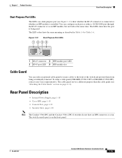
... documentation or the release note for more information about configuring speed and duplex settings for a dual-purpose uplink, see the software configuration guide. Front Panel Description Chapter 1 Product Overview Many legacy powered devices, including older Cisco IP phones and access points that first links up.
... documentation or the release note for more information about configuring speed and duplex settings for a dual-purpose uplink, see the software configuration guide. Front Panel Description Chapter 1 Product Overview Many legacy powered devices, including older Cisco IP phones and access points that first links up.

Hardware Installation Guide
Page 21
... the LEDs described here are visible in the embedded device manager and Network Assistant GUIs. System is not functioning properly. Chapter 1 Product Overview Front Panel Description LEDs You can use to configure and monitor individual switches and switch clusters. Table 1-2 Color Off Green Amber System LED System Status System is only...
... the LEDs described here are visible in the embedded device manager and Network Assistant GUIs. System is not functioning properly. Chapter 1 Product Overview Front Panel Description LEDs You can use to configure and monitor individual switches and switch clusters. Table 1-2 Color Off Green Amber System LED System Status System is only...
Hardware Installation Guide
Page 22
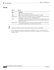
...Note The Catalyst 3560-8PC and Catalyst 3560-12PC-S switches do not have failed. If it is connected and ready to a neighboring device). Contact Cisco. RPS is providing power to another device (redundancy has been allocated to provide back-up power, if required. RPS is connected but is unavailable... because it does not, the RPS fan might have an RPS LED. Front Panel Description Chapter 1 Product Overview RPS LED Table 1-3 RPS LED Color Off Green Blinking green Amber Blinking amber RPS Status RPS is off or not ...
...Note The Catalyst 3560-8PC and Catalyst 3560-12PC-S switches do not have failed. If it is connected and ready to a neighboring device). Contact Cisco. RPS is providing power to another device (redundancy has been allocated to provide back-up power, if required. RPS is connected but is unavailable... because it does not, the RPS fan might have an RPS LED. Front Panel Description Chapter 1 Product Overview RPS LED Table 1-3 RPS LED Color Off Green Blinking green Amber Blinking amber RPS Status RPS is off or not ...

Hardware Installation Guide
Page 23
...PoE mode is not selected, the PoE LED shows PoE problems when they are in half-duplex mode. Chapter 1 Product Overview Front Panel Description Port LEDs and Modes The port LEDs, as a group or individually, display information about the switch and about the individual ports: Table 1-4... Modes for Port LEDs Selected Mode LED Port Mode Description STAT Port status The port status. Even if the PoE mode is not selected. None of the ports has a PoE fault. Table 1-6 ...
...PoE mode is not selected, the PoE LED shows PoE problems when they are in half-duplex mode. Chapter 1 Product Overview Front Panel Description Port LEDs and Modes The port LEDs, as a group or individually, display information about the switch and about the individual ports: Table 1-4... Modes for Port LEDs Selected Mode LED Port Mode Description STAT Port status The port status. Even if the PoE mode is not selected. None of the ports has a PoE fault. Table 1-6 ...

Hardware Installation Guide
Page 24
... port. Blinking green Port is not sending or receiving packets. Note When installed in Catalyst 3560 switches, 1000BASE-T SFP modules can be used to connect Cisco prestandard IP Phones or wireless access points or IEEE 802.3af-compliant devices to PoE ports. Port is operating at 100 Mb/s. Green Port is... green and amber Blinking amber If the powered device is receiving power from the network the cable or device that causes a PoE fault. Front Panel Description Chapter 1 Product Overview Table 1-6 Port Mode PoE Meaning of Port LED Colors in Different Modes on .
... port. Blinking green Port is not sending or receiving packets. Note When installed in Catalyst 3560 switches, 1000BASE-T SFP modules can be used to connect Cisco prestandard IP Phones or wireless access points or IEEE 802.3af-compliant devices to PoE ports. Port is operating at 100 Mb/s. Green Port is... green and amber Blinking amber If the powered device is receiving power from the network the cable or device that causes a PoE fault. Front Panel Description Chapter 1 Product Overview Table 1-6 Port Mode PoE Meaning of Port LED Colors in Different Modes on .
Hardware Installation Guide
Page 25
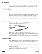
... installed. The LEDs show whether the RJ-45 connector is connected or whether an SFP module is being accidentally removed. Rear Panel Description • Internal Power Supply, page 1-18 • Cisco RPS, page 1-19 • Console Port, page 1-19 • Security Slots, page 1-20 Note The Catalyst 3560-8PC and the Catalyst...
... installed. The LEDs show whether the RJ-45 connector is connected or whether an SFP module is being accidentally removed. Rear Panel Description • Internal Power Supply, page 1-18 • Cisco RPS, page 1-19 • Console Port, page 1-19 • Security Slots, page 1-20 Note The Catalyst 3560-8PC and the Catalyst...

Hardware Installation Guide
Page 26
...Description Chapter 1 Product Overview The switch rear panel has an AC power connector, an RPS connector, and an RJ-45 console port. (See Figure 1-14, Figure 1-15, and Figure 1-16 for examples of the Catalyst 3560 rear panels.) Figure 1-14 Catalyst 3560-24PS[email protected] 97914 1 2 3 4 1 RJ-45 console port 3 RPS connector 2 AC power connector 4 Fan exhaust Figure 1-15 Catalyst 3560G-24PS, 3560G-48PS, 3560G-24TS, and 3560G-48TS Switch Rear Panel 119678 CONSOLE DSCPIENPCPOIUWFTIEESDRFISONURMPRPAELNYMUOATLE 12 3 4 1 RJ-45 console port 3 RPS connector 2 Fan ...
...Description Chapter 1 Product Overview The switch rear panel has an AC power connector, an RPS connector, and an RJ-45 console port. (See Figure 1-14, Figure 1-15, and Figure 1-16 for examples of the Catalyst 3560 rear panels.) Figure 1-14 Catalyst 3560-24PS[email protected] 97914 1 2 3 4 1 RJ-45 console port 3 RPS connector 2 AC power connector 4 Fan exhaust Figure 1-15 Catalyst 3560G-24PS, 3560G-48PS, 3560G-24TS, and 3560G-48TS Switch Rear Panel 119678 CONSOLE DSCPIENPCPOIUWFTIEESDRFISONURMPRPAELNYMUOATLE 12 3 4 1 RJ-45 console port 3 RPS connector 2 Fan ...

Hardware Installation Guide
Page 27
Chapter 1 Product Overview Rear Panel Description Figure 1-16 Catalyst 3560V2-24PS, 3560V2-48PS, 3560V2-24TS, 3560V2-48TS Switch Rear Panel 274670 CONSOLE 1 2 3 4 1 RJ-45 console port 2 Fan exhaust 3 RPS connector 4 AC power connector Figure 1-17 Catalyst 3560V2-24TS-SD Switch Rear Panel 274671 CONSOLE 12 3 4 1 RJ-45 console port 2 Fan exhaust 3 RPS connector 4 DC power connector OL-6337-07 Catalyst 3560 Switch Hardware Installation Guide 1-17
Chapter 1 Product Overview Rear Panel Description Figure 1-16 Catalyst 3560V2-24PS, 3560V2-48PS, 3560V2-24TS, 3560V2-48TS Switch Rear Panel 274670 CONSOLE 1 2 3 4 1 RJ-45 console port 2 Fan exhaust 3 RPS connector 4 AC power connector Figure 1-17 Catalyst 3560V2-24TS-SD Switch Rear Panel 274671 CONSOLE 12 3 4 1 RJ-45 console port 2 Fan exhaust 3 RPS connector 4 DC power connector OL-6337-07 Catalyst 3560 Switch Hardware Installation Guide 1-17

Hardware Installation Guide
Page 28
... dual feeds (A and B) that are diode-OR-ed into a single power block. For installation instructions, see Appendix C, "Connecting to an AC power outlet. Rear Panel Description Chapter 1 Product Overview The Catalyst 3560-8PC and Catalyst 3560-12PC-S rear panels have an AC power connector and heat sinks. (See Figure 1-18.) Figure...
... dual feeds (A and B) that are diode-OR-ed into a single power block. For installation instructions, see Appendix C, "Connecting to an AC power outlet. Rear Panel Description Chapter 1 Product Overview The Catalyst 3560-8PC and Catalyst 3560-12PC-S rear panels have an AC power connector and heat sinks. (See Figure 1-18.) Figure...
Hardware Installation Guide
Page 29
...cable. Note The Catalyst 3560-8PC and Catalyst 3560-12PC-S switches do not have an RPS connector. For complete information about the Cisco RPS products, including compatibility matrixes listing the supported RPS for each Catalyst 3560 switch, see the "Connector and Cable Specifications" section ...of a connected switch fails and provides power to the failed switch, preventing loss of network traffic. Chapter 1 Product Overview Rear Panel Description Cisco RPS Depending on the switch model, you need to provide an RJ-45-to-DB-25 female DTE adapter. Console Port You can...
...cable. Note The Catalyst 3560-8PC and Catalyst 3560-12PC-S switches do not have an RPS connector. For complete information about the Cisco RPS products, including compatibility matrixes listing the supported RPS for each Catalyst 3560 switch, see the "Connector and Cable Specifications" section ...of a connected switch fails and provides power to the failed switch, preventing loss of network traffic. Chapter 1 Product Overview Rear Panel Description Cisco RPS Depending on the switch model, you need to provide an RJ-45-to-DB-25 female DTE adapter. Console Port You can...