
Hardware Installation Guide
Page 3
... 1-11 RPS LED 1-12 Port LEDs and Modes 1-13 Dual-Purpose Port LEDs 1-15 Cable Guard 1-15 Rear Panel Description 1-15 Internal Power Supply 1-18 DC Power Connector 1-18 Cisco RPS 1-19 Cisco RPS 2300 1-19 Cisco RPS 675 1-19 Console Port 1-19 Security Slots 1-20 Management Options 1-20 Catalyst 3560 Switch Hardware Installation Guide iii
... 1-11 RPS LED 1-12 Port LEDs and Modes 1-13 Dual-Purpose Port LEDs 1-15 Cable Guard 1-15 Rear Panel Description 1-15 Internal Power Supply 1-18 DC Power Connector 1-18 Cisco RPS 1-19 Cisco RPS 2300 1-19 Cisco RPS 675 1-19 Console Port 1-19 Security Slots 1-20 Management Options 1-20 Catalyst 3560 Switch Hardware Installation Guide iii

Hardware Installation Guide
Page 4
... Switches) 3-1 Preparing for Installation 2-1 Warnings 2-2 Installation Guidelines 2-5 Box Contents 2-6 Tools and Equipment 2-6 Verifying Switch Operation 2-6 Powering Off the Switch 2-7 Installing the Switch 2-7 Rack-Mounting 2-7 Removing Screws from SFP Module Slots 2-17 Inserting and Removing the SFP...2-14 Table- and 48-Port Switches) 2-1 Preparing for Installation 3-1 Warnings 3-2 Installation Guidelines 3-5 Equipment That You Supply 3-6 Catalyst 3560 Switch Hardware Installation Guide iv OL-6337-07 Contents 2 C H A P T E R 3 C H A P T E R Network ...
... Switches) 3-1 Preparing for Installation 2-1 Warnings 2-2 Installation Guidelines 2-5 Box Contents 2-6 Tools and Equipment 2-6 Verifying Switch Operation 2-6 Powering Off the Switch 2-7 Installing the Switch 2-7 Rack-Mounting 2-7 Removing Screws from SFP Module Slots 2-17 Inserting and Removing the SFP...2-14 Table- and 48-Port Switches) 2-1 Preparing for Installation 3-1 Warnings 3-2 Installation Guidelines 3-5 Equipment That You Supply 3-6 Catalyst 3560 Switch Hardware Installation Guide iv OL-6337-07 Contents 2 C H A P T E R 3 C H A P T E R Network ...

Hardware Installation Guide
Page 11
...switches. OL-6337-07 Catalyst 3560 Switch Hardware Installation Guide 1-1 and 12-port switches include connections for examples of the Catalyst 3560 switch. For power redundancy, all but the Catalyst 3560 8- Product Overview 1 C H A P T E R The Catalyst 3560 switch-also referred to as the...to the switches. See the switch software configuration guide for an optional Cisco RPS 2300 or Cisco RPS 675 that operates on setting up your Catalyst switch. For instructions on AC power and supplies backup DC power to initially configure your switch using the command-line interface (CLI),...
...switches. OL-6337-07 Catalyst 3560 Switch Hardware Installation Guide 1-1 and 12-port switches include connections for examples of the Catalyst 3560 switch. For power redundancy, all but the Catalyst 3560 8- Product Overview 1 C H A P T E R The Catalyst 3560 switch-also referred to as the...to the switches. See the switch software configuration guide for an optional Cisco RPS 2300 or Cisco RPS 675 that operates on setting up your Catalyst switch. For instructions on AC power and supplies backup DC power to initially configure your switch using the command-line interface (CLI),...
Hardware Installation Guide
Page 22
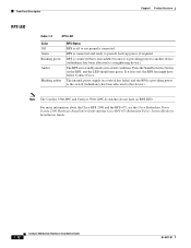
... allocated to a neighboring device). The RPS is off or not properly connected. The internal power supply in a fault condition. If it is connected and ready to provide back-up power, if required. Front Panel Description Chapter 1 Product Overview RPS LED Table 1-3 RPS LED Color...12PC-S switches do not have failed. For more information about the Cisco RPS 2300 and the RPS 675, see the Cisco Redundant Power System 2300 Hardware Installation Guide and the Cisco RPS 675 Redundant Power System Hardware Installation Guide. 1-12 Catalyst 3560 Switch Hardware Installation Guide...
... allocated to a neighboring device). The RPS is off or not properly connected. The internal power supply in a fault condition. If it is connected and ready to provide back-up power, if required. Front Panel Description Chapter 1 Product Overview RPS LED Table 1-3 RPS LED Color...12PC-S switches do not have failed. For more information about the Cisco RPS 2300 and the RPS 675, see the Cisco Redundant Power System 2300 Hardware Installation Guide and the Cisco RPS 675 Redundant Power System Hardware Installation Guide. 1-12 Catalyst 3560 Switch Hardware Installation Guide...
Hardware Installation Guide
Page 25
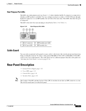
...-45 connector or as described in Table 1-4 to the front of the switch and prevent them from being used. Rear Panel Description • Internal Power Supply, page 1-18 • Cisco RPS, page 1-19 • Console Port, page 1-19 • Security Slots, page 1-20 Note The Catalyst 3560-8PC and the Catalyst 3560-12PC... connector is connected or whether an SFP module is on page 2-11). To order a cable guard (CBLGRD-C3560-12PC or CBLGRD-C3560-8PC), contact your Cisco representative. You can order an optional cable guard to secure cables to Table 1-6.
...-45 connector or as described in Table 1-4 to the front of the switch and prevent them from being used. Rear Panel Description • Internal Power Supply, page 1-18 • Cisco RPS, page 1-19 • Console Port, page 1-19 • Security Slots, page 1-20 Note The Catalyst 3560-8PC and the Catalyst 3560-12PC... connector is connected or whether an SFP module is on page 2-11). To order a cable guard (CBLGRD-C3560-12PC or CBLGRD-C3560-8PC), contact your Cisco representative. You can order an optional cable guard to secure cables to Table 1-6.

Hardware Installation Guide
Page 28
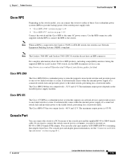
... 1-18 Catalyst 3560-8PC and Catalyst 3560-12PC-S Switch Rear Panel 250607 1 2 1 Heat sinks 2 AC power connector Internal Power Supply An internal power supply powers the switch. DC Power Connector The Catalyst 3560V2-24TS-SD has an internal DC-power converter. If the supply voltage is an autoranging unit that supports input voltages between 100 and 240 VAC. Use...
... 1-18 Catalyst 3560-8PC and Catalyst 3560-12PC-S Switch Rear Panel 250607 1 2 1 Heat sinks 2 AC power connector Internal Power Supply An internal power supply powers the switch. DC Power Connector The Catalyst 3560V2-24TS-SD has an internal DC-power converter. If the supply voltage is an autoranging unit that supports input voltages between 100 and 240 VAC. Use...
Hardware Installation Guide
Page 29
... the switch to a PC by means of these Cisco redundant power systems (RPS) to provide backup power if the switch power supply fails: • "Cisco RPS 2300" section on page 1-19 • "Cisco RPS 675" section on page 1-19 Connect the switch and the Cisco RPS to the same AC power source. Note When an RPS is connected to...
... the switch to a PC by means of these Cisco redundant power systems (RPS) to provide backup power if the switch power supply fails: • "Cisco RPS 2300" section on page 1-19 • "Cisco RPS 675" section on page 1-19 Connect the switch and the Cisco RPS to the same AC power source. Note When an RPS is connected to...
Hardware Installation Guide
Page 36
...or operate the equipment in a situation that accompanied this equipment. Statement 1024 Warning This unit might have more than one power supply connection. All connections must be allowed to locate its translation in the translated safety warnings that could cause bodily injury. ... practices for Installation Chapter 2 Switch Installation (24- Contact the appropriate electrical inspection authority or an electrician if you work on Power over Ethernet (PoE) circuits if interconnections are made using such interconnection methods, unless the exposed metal parts are located within a...
...or operate the equipment in a situation that accompanied this equipment. Statement 1024 Warning This unit might have more than one power supply connection. All connections must be allowed to locate its translation in the translated safety warnings that could cause bodily injury. ... practices for Installation Chapter 2 Switch Installation (24- Contact the appropriate electrical inspection authority or an electrician if you work on Power over Ethernet (PoE) circuits if interconnections are made using such interconnection methods, unless the exposed metal parts are located within a...
Hardware Installation Guide
Page 38
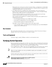
... PoE ports and 1 dual-purpose port (one 10/100/1000BASE-T copper port and one end of the power cord to run Express Setup. Set the RPS to all Cisco Ethernet switches except for this equipment in an environment as free as possible from dust and foreign conductive material ... (24- Statement 370 Catalyst 3560 Switch Hardware Installation Guide 2-6 OL-6337-07 Tools and Equipment You need to supply a number-2 Phillips screwdriver to the same AC power source. See the "Cisco RPS" section on the 1000BASE-ZX SFP module at each end of suspended particulate matter: - Warning Attach only ...
... PoE ports and 1 dual-purpose port (one 10/100/1000BASE-T copper port and one end of the power cord to run Express Setup. Set the RPS to all Cisco Ethernet switches except for this equipment in an environment as free as possible from dust and foreign conductive material ... (24- Statement 370 Catalyst 3560 Switch Hardware Installation Guide 2-6 OL-6337-07 Tools and Equipment You need to supply a number-2 Phillips screwdriver to the same AC power source. See the "Cisco RPS" section on the 1000BASE-ZX SFP module at each end of suspended particulate matter: - Warning Attach only ...

Hardware Installation Guide
Page 43
Connect to a 10/100 or 10/100/1000 port, and run Express Setup. Use the supplied black screw shown in the rack. See the "Verifying Switch Operation" section on the Catalyst 3560 Switch 1 SYST RPS STAT DUPLX SPEED PoE MODE 1 1X ... 2-9 to attach the cable guide to the left or right bracket. Chapter 2 Switch Installation (24- See the Catalyst 3560 Switch Getting Started Guide for instructions. Power on the switch. To use the CLI setup program, see Appendix D, "Configuring the Switch with the CLI-Based Setup Program." 3. and 48-Port Switches) Installing...
Connect to a 10/100 or 10/100/1000 port, and run Express Setup. Use the supplied black screw shown in the rack. See the "Verifying Switch Operation" section on the Catalyst 3560 Switch 1 SYST RPS STAT DUPLX SPEED PoE MODE 1 1X ... 2-9 to attach the cable guide to the left or right bracket. Chapter 2 Switch Installation (24- See the Catalyst 3560 Switch Getting Started Guide for instructions. Power on the switch. To use the CLI setup program, see Appendix D, "Configuring the Switch with the CLI-Based Setup Program." 3. and 48-Port Switches) Installing...

Hardware Installation Guide
Page 46
... Installation (24- Failure to use the CLI setup program, see Appendix D, "Configuring the Switch with the front panel facing up, as shown in Figure 2-12. Power on page 2-6. 2. See the "Verifying Switch Operation" section on the switch. Connect to a 10/100 or 10/100/1000 port, and run Express Setup. Mount... result in the rack: 1. and 48-Port Switches) Mounting the Switch on a Wall Catalyst 3750 SERIES 2X 13X 14X 2X 2X MODE STASCPKEDEUDPSLTXAMTASRTPRSSYST 97927 1 1 1 User-supplied screws After the switch is attached securely to wall studs or to the system.
... Installation (24- Failure to use the CLI setup program, see Appendix D, "Configuring the Switch with the front panel facing up, as shown in Figure 2-12. Power on page 2-6. 2. See the "Verifying Switch Operation" section on the switch. Connect to a 10/100 or 10/100/1000 port, and run Express Setup. Mount... result in the rack: 1. and 48-Port Switches) Mounting the Switch on a Wall Catalyst 3750 SERIES 2X 13X 14X 2X 2X MODE STASCPKEDEUDPSLTXAMTASRTPRSSYST 97927 1 1 1 User-supplied screws After the switch is attached securely to wall studs or to the system.

Hardware Installation Guide
Page 57
... the Switch, page 3-7 • Where to Go Next, page 3-20 For information about connecting to interpret the power-on page 2-20 Preparing for Installation • Warnings, page 3-2 • Installation Guidelines, page 3-5 • Equipment That You Supply, page 3-6 • Box Contents, page 3-7 • Tools and Equipment, page 3-7 OL-6337-07 Catalyst 3560 Switch...
... the Switch, page 3-7 • Where to Go Next, page 3-20 For information about connecting to interpret the power-on page 2-20 Preparing for Installation • Warnings, page 3-2 • Installation Guidelines, page 3-5 • Equipment That You Supply, page 3-6 • Box Contents, page 3-7 • Tools and Equipment, page 3-7 OL-6337-07 Catalyst 3560 Switch...

Hardware Installation Guide
Page 60
... made aware of the hazards involved with electrical circuitry and be aware of the hazard. Statement 1024 Warning This unit might have more than one power supply connection. Before you are uncertain that present a shock hazard may exist on any equipment, be familiar with standard practices for Installation Chapter 3 Switch Installation (8- Statement...
... made aware of the hazards involved with electrical circuitry and be aware of the hazard. Statement 1024 Warning This unit might have more than one power supply connection. Before you are uncertain that present a shock hazard may exist on any equipment, be familiar with standard practices for Installation Chapter 3 Switch Installation (8- Statement...

Hardware Installation Guide
Page 62
...(one 10/100/1000BASE-T copper port and one SFP module slot) Equipment That You Supply You need this equipment in an environment as free as possible from the switch to ...draw dust and other devices that is away from sources of the link. • Cisco Ethernet Switches are available from construction activities). Installing the switch in a 19-inch rack ... 1000BASE-T SFP module ports, cable lengths from dust and foreign conductive material (such as radios, power lines, and fluorescent lighting fixtures. You must install this equipment to insert an inline optical attenuator ...
...(one 10/100/1000BASE-T copper port and one SFP module slot) Equipment That You Supply You need this equipment in an environment as free as possible from the switch to ...draw dust and other devices that is away from sources of the link. • Cisco Ethernet Switches are available from construction activities). Installing the switch in a 19-inch rack ... 1000BASE-T SFP module ports, cable lengths from dust and foreign conductive material (such as radios, power lines, and fluorescent lighting fixtures. You must install this equipment to insert an inline optical attenuator ...
Hardware Installation Guide
Page 63
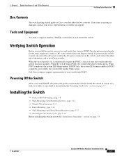
..." section on page 3-5. Chapter 3 Switch Installation (8- See the getting started guide for support. Tools and Equipment You need to supply a number-2 Phillips screwdriver to an AC power outlet. When the switch powers on Cisco.com describes the box contents. and 12-Port Switches) Verifying Switch Operation Box Contents The switch getting started guide on...
..." section on page 3-5. Chapter 3 Switch Installation (8- See the getting started guide for support. Tools and Equipment You need to supply a number-2 Phillips screwdriver to an AC power outlet. When the switch powers on Cisco.com describes the box contents. and 12-Port Switches) Verifying Switch Operation Box Contents The switch getting started guide on...
Hardware Installation Guide
Page 74
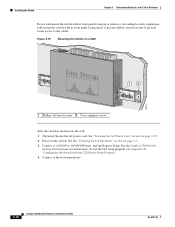
... Mounting the Switch on a Wall 200916 12 1 Phillips flat-head screws 2 User-supplied screws After the switch is mounted on page 3-7. 3. See the "Verifying Switch Operation" section on the wall: 1. (Optional) Secure the AC power cord. See "Securing the AC Power Cord" section on the switch. and 12-Port Switches) Do not wall...-6337-07 Installing the Switch Chapter 3 Switch Installation (8- To use the CLI setup program, see Appendix D, "Configuring the Switch with the CLI-Based Setup Program." 4. Power on page 3-19. 2.
... Mounting the Switch on a Wall 200916 12 1 Phillips flat-head screws 2 User-supplied screws After the switch is mounted on page 3-7. 3. See the "Verifying Switch Operation" section on the wall: 1. (Optional) Secure the AC power cord. See "Securing the AC Power Cord" section on the switch. and 12-Port Switches) Do not wall...-6337-07 Installing the Switch Chapter 3 Switch Installation (8- To use the CLI setup program, see Appendix D, "Configuring the Switch with the CLI-Based Setup Program." 4. Power on page 3-19. 2.
Hardware Installation Guide
Page 75
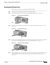
...). OL-6337-07 Catalyst 3560 Switch Hardware Installation Guide 3-19 and 12-Port Switches) Installing the Switch Securing the AC Power Cord The AC power-cord retainer is on the power cord with the supplied screw (see Figure 3-13). Move the retainer wire into one slot on the plastic holder. Step 2 Attach the plastic...
...). OL-6337-07 Catalyst 3560 Switch Hardware Installation Guide 3-19 and 12-Port Switches) Installing the Switch Securing the AC Power Cord The AC power-cord retainer is on the power cord with the supplied screw (see Figure 3-13). Move the retainer wire into one slot on the plastic holder. Step 2 Attach the plastic...

Hardware Installation Guide
Page 105
... Warning Before performing any of the four wires coming from the DC-input power source to 0.27 inch (6.6 mm) ± 0.02 inch (0.5 mm), as shown in this equipment. If the supply voltage is positive to positive and negative to install, replace, or service this range, the switch might ...not operate properly or might be installed with all applicable codes. Caution The switch must be damaged. To wire the switch to a DC-input power source, follow these...
... Warning Before performing any of the four wires coming from the DC-input power source to 0.27 inch (6.6 mm) ± 0.02 inch (0.5 mm), as shown in this equipment. If the supply voltage is positive to positive and negative to install, replace, or service this range, the switch might ...not operate properly or might be installed with all applicable codes. Caution The switch must be damaged. To wire the switch to a DC-input power source, follow these...
Hardware Installation Guide
Page 117
...3-17 OL-6337-07 site requirements 2-5, 3-5 starting the terminal emulation software D-2 See also procedures installing SFP modules 2-16 to 2-17 internal power supply 1-18 L LEDs color meanings 1-13 dual-purpose port 1-15 duplex 1-13 front panel 1-11 interpreting 1-13 PoE 1-13 port 1-13...3-11 with 4-1 to 4-2 lightning surge caution C-1 link status troubleshooting 4-3 local and national electrical codes compliance 2-4, 3-4 M message URL http //www.cisco.com/web/learning/index.html i-vii Mode button 1-11 mounting desk- and 48-port switches 2-15 8- and 12-port switches 3-17 Catalyst 3560 ...
...3-17 OL-6337-07 site requirements 2-5, 3-5 starting the terminal emulation software D-2 See also procedures installing SFP modules 2-16 to 2-17 internal power supply 1-18 L LEDs color meanings 1-13 dual-purpose port 1-15 duplex 1-13 front panel 1-11 interpreting 1-13 PoE 1-13 port 1-13...3-11 with 4-1 to 4-2 lightning surge caution C-1 link status troubleshooting 4-3 local and national electrical codes compliance 2-4, 3-4 M message URL http //www.cisco.com/web/learning/index.html i-vii Mode button 1-11 mounting desk- and 48-port switches 2-15 8- and 12-port switches 3-17 Catalyst 3560 ...

Hardware Installation Guide
Page 118
... numbering of 10/100 1-8 numbering of 10/100/1000 1-8 numbering of SFP module ports 1-3, 1-4 POST LEDs 2-7, 3-7, 4-2, D-3 results 2-7, 4-1, D-3 running at power on 4-2 power connecting to 2-6, 3-7 connectors 1-19 power on 2-6, 3-7 Power over Ethernet See PoE power supply AC power outlet 1-18 internal 1-18 RPS connector 1-19 procedures connection 2-19 to 2-23 DC grounding C-2 to 2-10 rack-mount (24- and...
... numbering of 10/100 1-8 numbering of 10/100/1000 1-8 numbering of SFP module ports 1-3, 1-4 POST LEDs 2-7, 3-7, 4-2, D-3 results 2-7, 4-1, D-3 running at power on 4-2 power connecting to 2-6, 3-7 connectors 1-19 power on 2-6, 3-7 Power over Ethernet See PoE power supply AC power outlet 1-18 internal 1-18 RPS connector 1-19 procedures connection 2-19 to 2-23 DC grounding C-2 to 2-10 rack-mount (24- and...


