
Installation Guide
Page 3
... Switch Models 1-2 Front-Panel Description 1-2 10/100 Ports 1-5 Dual-Purpose Ports 1-5 100BASE-FX Ports 1-5 Power and Relay Connector 1-5 Console Port 1-6 LEDs 1-6 Setup LED 1-8 System LED 1-9 Alarm LED 1-9 Power Status LED 1-9 10/100 Port Status LEDs 1-10 100Base-FX Port Status LEDs 1-10 Dual-Purpose Port... LEDs 1-11 Compact Flash Memory Card 1-11 Rear-Panel Description 1-12 Power Converter (Optional) 1-13 Management Options 1-14 Network Configurations...
... Switch Models 1-2 Front-Panel Description 1-2 10/100 Ports 1-5 Dual-Purpose Ports 1-5 100BASE-FX Ports 1-5 Power and Relay Connector 1-5 Console Port 1-6 LEDs 1-6 Setup LED 1-8 System LED 1-9 Alarm LED 1-9 Power Status LED 1-9 10/100 Port Status LEDs 1-10 100Base-FX Port Status LEDs 1-10 Dual-Purpose Port... LEDs 1-11 Compact Flash Memory Card 1-11 Rear-Panel Description 1-12 Power Converter (Optional) 1-13 Management Options 1-14 Network Configurations...

Installation Guide
Page 4
... Installing the Switch in a Rack 2-29 Removing the Switch from a DIN Rail or a Rack 2-31 Connecting Power and Alarm Circuits 2-32 Wiring the Protective Ground and DC Power 2-32 Wiring the External Alarms 2-33 Connecting Destination Ports 2-36 Connecting to 10/100 and 10/100/1000 Ports...43 Connecting the Switch to the Power Converter 2-44 Attaching the Power Converter to the Switch 2-45 Installing the Power Converter on a DIN Rail, Wall, or Rack Adapter 2-46 Connecting the DC Power Clip 2-46 Connecting the Power Converter to an AC Power Source 2-47 Cisco IE 3000 Switch Hardware Installation Guide...
... Installing the Switch in a Rack 2-29 Removing the Switch from a DIN Rail or a Rack 2-31 Connecting Power and Alarm Circuits 2-32 Wiring the Protective Ground and DC Power 2-32 Wiring the External Alarms 2-33 Connecting Destination Ports 2-36 Connecting to 10/100 and 10/100/1000 Ports...43 Connecting the Switch to the Power Converter 2-44 Attaching the Power Converter to the Switch 2-45 Installing the Power Converter on a DIN Rail, Wall, or Rack Adapter 2-46 Connecting the DC Power Clip 2-46 Connecting the Power Converter to an AC Power Source 2-47 Cisco IE 3000 Switch Hardware Installation Guide...

Installation Guide
Page 5
... E R A A P P E N D I X B A P P E N D I X OL-13017-01 Preparing the AC Power Cord 2-47 Connecting the AC Power Cord to the Power Converter 2-48 Connecting the Power Converter to a DC Power Source 2-51 Applying Power to the Power Converter 2-53 Where to Go Next 2-53 Troubleshooting 3-1 Diagnosing Problems 3-1 Verify Switch POST Results 3-1 Verify Switch LEDs 3-2 Verify Switch Connections 3-2 ... Installation Guidelines B-5 Environment and Enclosure Guidelines: B-5 Other Guidelines B-6 Verifying Package Contents B-7 Adding Modules to the Switch B-8 Cisco IE 3000 Switch Hardware Installation Guide v
... E R A A P P E N D I X B A P P E N D I X OL-13017-01 Preparing the AC Power Cord 2-47 Connecting the AC Power Cord to the Power Converter 2-48 Connecting the Power Converter to a DC Power Source 2-51 Applying Power to the Power Converter 2-53 Where to Go Next 2-53 Troubleshooting 3-1 Diagnosing Problems 3-1 Verify Switch POST Results 3-1 Verify Switch LEDs 3-2 Verify Switch Connections 3-2 ... Installation Guidelines B-5 Environment and Enclosure Guidelines: B-5 Other Guidelines B-6 Verifying Package Contents B-7 Adding Modules to the Switch B-8 Cisco IE 3000 Switch Hardware Installation Guide v
Installation Guide
Page 6
..., or Rack Adapter B-52 Connecting the DC Power Clip B-52 Connecting the Power Converter to an AC Power Source B-53 Preparing the AC Power Cord B-53 Connecting the AC Power Cord to the Power Converter B-54 Connecting the Power Converter to a DC Power Source B-57 Applying Power to the Power Converter B-59 Cisco IE 3000 Switch Hardware Installation Guide vi OL...
..., or Rack Adapter B-52 Connecting the DC Power Clip B-52 Connecting the Power Converter to an AC Power Source B-53 Preparing the AC Power Cord B-53 Connecting the AC Power Cord to the Power Converter B-54 Connecting the Power Converter to a DC Power Source B-57 Applying Power to the Power Converter B-59 Cisco IE 3000 Switch Hardware Installation Guide vi OL...
Installation Guide
Page 11
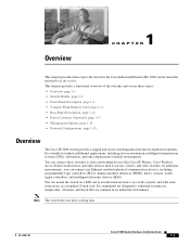
... to withstand extremes in temperature, vibration, and shock that describe the Cisco Industrial Ethernet (IE) 3000 switch, hereafter referred to office networking devices like Cisco IP Phones, Cisco Wireless Access Points workstations, and other devices such as the switch. Note...Memory Card, page 1-11 • Rear-Panel Description, page 1-12 • Power Converter (Optional), page 1-13 • Management Options, page 1-14 • Network Configurations, page 1-15 Overview The Cisco IE 3000 switch provides a rugged and secure switching infrastructure for industrial Ethernet applications, ...
... to withstand extremes in temperature, vibration, and shock that describe the Cisco Industrial Ethernet (IE) 3000 switch, hereafter referred to office networking devices like Cisco IP Phones, Cisco Wireless Access Points workstations, and other devices such as the switch. Note...Memory Card, page 1-11 • Rear-Panel Description, page 1-12 • Power Converter (Optional), page 1-13 • Management Options, page 1-14 • Network Configurations, page 1-15 Overview The Cisco IE 3000 switch provides a rugged and secure switching infrastructure for industrial Ethernet applications, ...

Installation Guide
Page 12
... front panel and includes these sections: • 10/100 Ports, page 1-5 • Dual-Purpose Ports, page 1-5 • 100BASE-FX Ports, page 1-5 • Power and Relay Connector, page 1-5 • Console Port, page 1-6 • LEDs, page 1-6 The switch front panel contains the ports, the LEDs, and the... power and relay connectors. Cisco IE 3000 Switch Hardware Installation Guide 1-2 OL-13017-01 Figure 1-1 to increase the number of ports. The Cisco IE-3000-4TC and the Cisco IE-3000-8TC are the switch models, and the Cisco IEM-3000-8TM and the Cisco IEM-3000-8FM are expansion...
... front panel and includes these sections: • 10/100 Ports, page 1-5 • Dual-Purpose Ports, page 1-5 • 100BASE-FX Ports, page 1-5 • Power and Relay Connector, page 1-5 • Console Port, page 1-6 • LEDs, page 1-6 The switch front panel contains the ports, the LEDs, and the... power and relay connectors. Cisco IE 3000 Switch Hardware Installation Guide 1-2 OL-13017-01 Figure 1-1 to increase the number of ports. The Cisco IE-3000-4TC and the Cisco IE-3000-8TC are the switch models, and the Cisco IEM-3000-8TM and the Cisco IEM-3000-8FM are expansion...

Installation Guide
Page 13
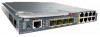
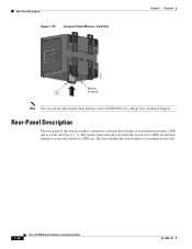
Chapter 1 Overview Figure 1-1 Cisco IE-3000-8TC Switch 1 2 Front-Panel Description 201699 3 45 1 Power and relay connectors 4 10/100 ports 2 Console port 5 Protective ground connection 3 Dual-purpose ports Figure 1-2 Cisco IE-3000-4TC Switch 1 2 201700 3 45 1 Power and relay connectors 4 2 Console port 5 3 Dual-purpose ports 10/100 ports Protective ground connection OL-13017-01 Cisco IE 3000 Switch Hardware Installation Guide 1-3
Chapter 1 Overview Figure 1-1 Cisco IE-3000-8TC Switch 1 2 Front-Panel Description 201699 3 45 1 Power and relay connectors 4 10/100 ports 2 Console port 5 Protective ground connection 3 Dual-purpose ports Figure 1-2 Cisco IE-3000-4TC Switch 1 2 201700 3 45 1 Power and relay connectors 4 2 Console port 5 3 Dual-purpose ports 10/100 ports Protective ground connection OL-13017-01 Cisco IE 3000 Switch Hardware Installation Guide 1-3

Installation Guide
Page 15
... both ports are field-replaceable, providing the uplink interfaces when inserted in length. Power and Relay Connector You connect the DC power and alarm signals to enable the automatic medium-dependent interface crossover (auto-MDIX) feature. OL-13017-01 Cisco IE 3000 Switch Hardware Installation Guide 1-5 When connecting the switch to workstations, servers...
... both ports are field-replaceable, providing the uplink interfaces when inserted in length. Power and Relay Connector You connect the DC power and alarm signals to enable the automatic medium-dependent interface crossover (auto-MDIX) feature. OL-13017-01 Cisco IE 3000 Switch Hardware Installation Guide 1-5 When connecting the switch to workstations, servers...

Installation Guide
Page 16
... to a PC through the GUI management applications-the Cisco Network Assistant application for multiple switches and the device manager GUI for environmental, power supply, and port status alarm conditions and can operate with a single power source or with either open . The switch software ...monitor the switch status, activity, and performance. These connectors provide screw terminals for instructions on the power and relay connector are operational, the switch draws power from Cisco Systems. For console-port and adapter-pinout information, see the "Two Twisted-Pair Cable Pinouts" ...
... to a PC through the GUI management applications-the Cisco Network Assistant application for multiple switches and the device manager GUI for environmental, power supply, and port status alarm conditions and can operate with a single power source or with either open . The switch software ...monitor the switch status, activity, and performance. These connectors provide screw terminals for instructions on the power and relay connector are operational, the switch draws power from Cisco Systems. For console-port and adapter-pinout information, see the "Two Twisted-Pair Cable Pinouts" ...

Installation Guide
Page 19
...source powers the switch, and the corresponding power status LED is green. If power is present on the circuit, or the system is off . If the switch has dual power sources, the switch draws power from the power source with one of the corresponding DC input. OL-13017-01 Cisco IE ...3000 Switch Hardware Installation Guide 1-9 Alarm LED Table 1-4 lists the alarm LED colors and their meanings. Table 1-5 Power Status LEDs Color Off ...
...source powers the switch, and the corresponding power status LED is green. If power is present on the circuit, or the system is off . If the switch has dual power sources, the switch draws power from the power source with one of the corresponding DC input. OL-13017-01 Cisco IE ...3000 Switch Hardware Installation Guide 1-9 Alarm LED Table 1-4 lists the alarm LED colors and their meanings. Table 1-5 Power Status LEDs Color Off ...

Installation Guide
Page 20
... LEDs only show that the power status LEDs do not oscillate at the switch input exceeds the valid level. Alternating green-amber Link fault. Link is disabled. 1-10 Cisco IE 3000 Switch Hardware Installation Guide OL-13017-01 Link is present. Blinking amber A link blocked by ...in Figure 1-6, Figure 1-7, and Figure 1-8. Activity. Blinking green Activity. Port is sending or receiving data. The difference, or hysteresis, ensures that power is not present on page 2-11. 10/100 Port Status LEDs Each 10/100 port has a port status LED, also called a port LED,...
... LEDs only show that the power status LEDs do not oscillate at the switch input exceeds the valid level. Alternating green-amber Link fault. Link is disabled. 1-10 Cisco IE 3000 Switch Hardware Installation Guide OL-13017-01 Link is present. Blinking amber A link blocked by ...in Figure 1-6, Figure 1-7, and Figure 1-8. Activity. Blinking green Activity. Port is sending or receiving data. The difference, or hysteresis, ensures that power is not present on page 2-11. 10/100 Port Status LEDs Each 10/100 port has a port status LED, also called a port LED,...
Installation Guide
Page 22
...Description Figure 1-10 Compact Flash Memory Card Slot Chapter 1 Overview 201832 Bottom 1 of the switch, modules, and power converter have latches for installation on the wall. 1-12 Cisco IE 3000 Switch Hardware Installation Guide OL-13017-01 Rear-Panel Description The rear panel of switch Note You can... obtain replacement flash memory cards (CF-IE3000=) by calling Cisco Technical Support. The latches slide outward to position the switch over a DIN rail and slide inward to secure the switch to a DIN...
...Description Figure 1-10 Compact Flash Memory Card Slot Chapter 1 Overview 201832 Bottom 1 of the switch, modules, and power converter have latches for installation on the wall. 1-12 Cisco IE 3000 Switch Hardware Installation Guide OL-13017-01 Rear-Panel Description The rear panel of switch Note You can... obtain replacement flash memory cards (CF-IE3000=) by calling Cisco Technical Support. The latches slide outward to position the switch over a DIN rail and slide inward to secure the switch to a DIN...
Installation Guide
Page 23
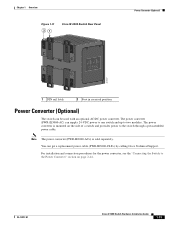
... installation and connection procedures for the power converter, see the "Connecting the Switch to the Power Converter" section on the side of a switch and provides power to two modules. The power converter (PWR-IE3000-AC) can get a replacement power cable (PWR-IE3000-CLP=) by calling Cisco Technical Support. Note The power converter (PWR-IE3000-AC=) is mounted...
... installation and connection procedures for the power converter, see the "Connecting the Switch to the Power Converter" section on the side of a switch and provides power to two modules. The power converter (PWR-IE3000-AC) can get a replacement power cable (PWR-IE3000-CLP=) by calling Cisco Technical Support. Note The power converter (PWR-IE3000-AC=) is mounted...
Installation Guide
Page 24
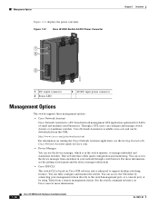
... can configure and manage switch clusters or standalone switches. Figure 1-12 Cisco IE 3000 Switch AC/DC Power Converter 1 2 3 Chapter 1 Overview 202314 1 DC output connector 2 Status LED 3 AC/DC input power connector Management Options The switch supports these management options: • Cisco Network Assistant Cisco Network Assistant is a PC-based network management GUI application optimized...
... can configure and manage switch clusters or standalone switches. Figure 1-12 Cisco IE 3000 Switch AC/DC Power Converter 1 2 3 Chapter 1 Overview 202314 1 DC output connector 2 Status LED 3 AC/DC input power connector Management Options The switch supports these management options: • Cisco Network Assistant Cisco Network Assistant is a PC-based network management GUI application optimized...
Installation Guide
Page 27
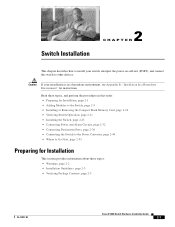
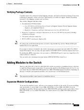
... Verifying Package Contents, page 2-5 OL-13017-01 Cisco IE 3000 Switch Hardware Installation Guide 2-1 Switch Installation 2 C H A P T E R This chapter describes how to install your installation is in this order: • Preparing for instructions. Caution If your switch, interpret the power-on self-test (POST), and connect the switch... Flash Memory Card, page 2-10 • Verifying Switch Operation, page 2-11 • Installing the Switch, page 2-23 • Connecting Power and Alarm Circuits, page 2-32 • Connecting Destination Ports, page 2-36 • Connecting the Switch to the...
... Verifying Package Contents, page 2-5 OL-13017-01 Cisco IE 3000 Switch Hardware Installation Guide 2-1 Switch Installation 2 C H A P T E R This chapter describes how to install your installation is in this order: • Preparing for instructions. Caution If your switch, interpret the power-on self-test (POST), and connect the switch... Flash Memory Card, page 2-10 • Verifying Switch Operation, page 2-11 • Installing the Switch, page 2-23 • Connecting Power and Alarm Circuits, page 2-32 • Connecting Destination Ports, page 2-36 • Connecting the Switch to the...
Installation Guide
Page 28
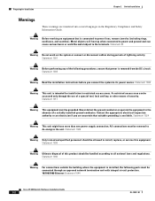
...power and ground and can be handled according to the terminals. Statement 1001 Warning Before performing any of the following ports must be removed to power... lines, remove jewelry (including rings, necklaces, and watches). Statement 1024 Warning This unit might have more than one power supply... the equipment is installed, the following procedures, ensure that power is intended for Installation Chapter 2 Switch Installation Warnings These ... access areas. All connections must be allowed to its power source. Statement 1028 Warning Only trained and qualified personnel ...
...power and ground and can be handled according to the terminals. Statement 1001 Warning Before performing any of the following ports must be removed to power... lines, remove jewelry (including rings, necklaces, and watches). Statement 1024 Warning This unit might have more than one power supply... the equipment is installed, the following procedures, ensure that power is intended for Installation Chapter 2 Switch Installation Warnings These ... access areas. All connections must be allowed to its power source. Statement 1028 Warning Only trained and qualified personnel ...
Installation Guide
Page 30
...an attached device cannot exceed 6562 ft (2 km). • Operating environment is only suitable for unrestricted cabling. - Front-panel direct current (DC) power and relay connector is within the ranges listed in Class I, Division 2, Groups A, B, C, D, or nonhazardous locations. The use in Appendix A, ...8226; Before installing the switch, first verify that can corrode, oxidize, or are poor conductors can be the following minimum clearances: - Cisco IE 3000 Switch Hardware Installation Guide 2-4 OL-13017-01 Follow the procedures in . (90 mm) - To prevent the switch from a...
...an attached device cannot exceed 6562 ft (2 km). • Operating environment is only suitable for unrestricted cabling. - Front-panel direct current (DC) power and relay connector is within the ranges listed in Class I, Division 2, Groups A, B, C, D, or nonhazardous locations. The use in Appendix A, ...8226; Before installing the switch, first verify that can corrode, oxidize, or are poor conductors can be the following minimum clearances: - Cisco IE 3000 Switch Hardware Installation Guide 2-4 OL-13017-01 Follow the procedures in . (90 mm) - To prevent the switch from a...
Installation Guide
Page 31
...Getting Started Guide (in German) • Two power and relay connectors • RJ-45 to the Switch The Cisco IE-3000-4TC or the Cisco IE-3000-8TC switch can order a kit containing four spare latches (DINCLP-IE3000=) from Cisco. Note The expansion modules cannot operate as standalone devices...100BASE-FX port to 24 Fast Ethernet ports. Chapter 2 Switch Installation Adding Modules to the Switch Verifying Package Contents Carefully remove the contents from Cisco. If any item is shipped with that includes: - Return all packing materials to -DB-25 female DTE adapter. If you want to ...
...Getting Started Guide (in German) • Two power and relay connectors • RJ-45 to the Switch The Cisco IE-3000-4TC or the Cisco IE-3000-8TC switch can order a kit containing four spare latches (DINCLP-IE3000=) from Cisco. Note The expansion modules cannot operate as standalone devices...100BASE-FX port to 24 Fast Ethernet ports. Chapter 2 Switch Installation Adding Modules to the Switch Verifying Package Contents Carefully remove the contents from Cisco. If any item is shipped with that includes: - Return all packing materials to -DB-25 female DTE adapter. If you want to ...
Installation Guide
Page 37
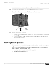
...See Figure 2-7. The card is keyed so that the switch passes the power-on the switch, and verify that you cannot insert it firmly in its final location, power on self-test (POST). These sections describe the steps required to connect ...a PC or terminal to the switch console port, to power on the bottom of switch Step 2 Install or remove the card, as desired: • To remove ...Terminal to the Console Port, page 2-12 • Verifying Switch Operation, page 2-11 OL-13017-01 Cisco IE 3000 Switch Hardware Installation Guide 2-11
...See Figure 2-7. The card is keyed so that the switch passes the power-on the switch, and verify that you cannot insert it firmly in its final location, power on self-test (POST). These sections describe the steps required to connect ...a PC or terminal to the switch console port, to power on the bottom of switch Step 2 Install or remove the card, as desired: • To remove ...Terminal to the Console Port, page 2-12 • Verifying Switch Operation, page 2-11 OL-13017-01 Cisco IE 3000 Switch Hardware Installation Guide 2-11
Installation Guide
Page 39
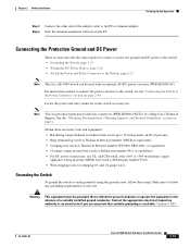
...these steps. and 18-gauge wires Grounding the Switch To ground the switch to the Switch, page 2-21 Note The Cisco IE 3000 switch can get replacement power and relay connectors (PWR-IE3000-CNCT=) by using the ground screw, follow any grounding requirements at your site. Statement ...the steps required to connect a protective ground and DC power to the switch: • Grounding the Switch, page 2-13 • Wiring the DC Power Source, page 2-16 • Attach the Power and Relay Connector to earth ground by calling Cisco Technical Support. Make sure to follow these necessary tools ...
...these steps. and 18-gauge wires Grounding the Switch To ground the switch to the Switch, page 2-21 Note The Cisco IE 3000 switch can get replacement power and relay connectors (PWR-IE3000-CNCT=) by using the ground screw, follow any grounding requirements at your site. Statement ...the steps required to connect a protective ground and DC power to the switch: • Grounding the Switch, page 2-13 • Wiring the DC Power Source, page 2-16 • Attach the Power and Relay Connector to earth ground by calling Cisco Technical Support. Make sure to follow these necessary tools ...


