

Owners Manual
Page 3
... Inches 48.0 cm • Depth Height 23 Inches 7.5 Inches 58.0 cm 19.0 cm 13.5 Inches 36.5 Incnes 34.0 cm 93.0 cm P.O. System Metric System U.S. • MA6 MIXER AMPLIFIER OPERATION INSTRUCTION MANUAL BY d MADE IN U.S.A.iSts°1.° • it141 zittl;id . BOX 4137 • 1300 EAST VALENCIA DRIVE • FULLERTON, CALIFORNIA 92634...
... Inches 48.0 cm • Depth Height 23 Inches 7.5 Inches 58.0 cm 19.0 cm 13.5 Inches 36.5 Incnes 34.0 cm 93.0 cm P.O. System Metric System U.S. • MA6 MIXER AMPLIFIER OPERATION INSTRUCTION MANUAL BY d MADE IN U.S.A.iSts°1.° • it141 zittl;id . BOX 4137 • 1300 EAST VALENCIA DRIVE • FULLERTON, CALIFORNIA 92634...
Owners Manual
Page 5
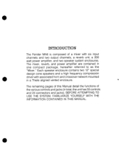
... 9 5 Master Section Reverb Return and Effects 5 Return Switches 9 5 Emphasizing One Instrument on 5 the Monitor Speakers 9 5 Equalizers 9 5 Explanation of the Equalizer Controls 10 5 Mixer Use 10 5 Use of an Additional Mixer 10 5 Effects Send and Receive Jacks 10 6 Monitor Out Jack 10 6 Auxiliary Reverb Send and Return Jacks 10 6 Pre-Amp Output Jack...
... 9 5 Master Section Reverb Return and Effects 5 Return Switches 9 5 Emphasizing One Instrument on 5 the Monitor Speakers 9 5 Equalizers 9 5 Explanation of the Equalizer Controls 10 5 Mixer Use 10 5 Use of an Additional Mixer 10 5 Effects Send and Receive Jacks 10 6 Monitor Out Jack 10 6 Auxiliary Reverb Send and Return Jacks 10 6 Pre-Amp Output Jack...
Owners Manual
Page 7
• INTRODUCTION The Fender MA6 is composed of the various controls and jacks (in total, the unit has 55 controls and 24 connectors and jacks). Each speaker enclosure contains two ... ATTEMPTING TO USE THE SYSTEM, FAMILIARIZE YOURSELF WITH THE INFORMATION CONTAINED IN THIS MANUAL. • The remaining pages of this Manual detail the functions of a mixer with associated horn and crossover network mounted in one compact package, hereafter referred to as the...
• INTRODUCTION The Fender MA6 is composed of the various controls and jacks (in total, the unit has 55 controls and 24 connectors and jacks). Each speaker enclosure contains two ... ATTEMPTING TO USE THE SYSTEM, FAMILIARIZE YOURSELF WITH THE INFORMATION CONTAINED IN THIS MANUAL. • The remaining pages of this Manual detail the functions of a mixer with associated horn and crossover network mounted in one compact package, hereafter referred to as the...

Owners Manual
Page 8
..., once the Gain Control has been set . INPUT CHANNEL CONTROL FUNCTIONS Gain Control (Fig. 3 - Item 2) This boosts or cuts the high frequency content of the Mixer to provide the optimum signal-to-noise ratio for frequency response curves. See Figure 4 for the par- Item 1) This adjusts the gain of the microphone...
..., once the Gain Control has been set . INPUT CHANNEL CONTROL FUNCTIONS Gain Control (Fig. 3 - Item 2) This boosts or cuts the high frequency content of the Mixer to provide the optimum signal-to-noise ratio for frequency response curves. See Figure 4 for the par- Item 1) This adjusts the gain of the microphone...

Owners Manual
Page 12
... jack allows use of a signal directly into the Main summing amplifier. The response of the five controls is discussed in Section II under "MIXER USE." PRE-AMP INPUT CONNECTORS ohms) microphone, and will most line level signals by reducing the channel Gain control. Item 1) This jack allows connection of a ...
... jack allows use of a signal directly into the Main summing amplifier. The response of the five controls is discussed in Section II under "MIXER USE." PRE-AMP INPUT CONNECTORS ohms) microphone, and will most line level signals by reducing the channel Gain control. Item 1) This jack allows connection of a ...
Owners Manual
Page 14
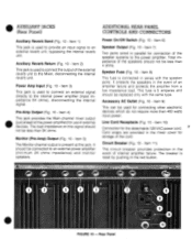
... not be less than 4 ohms. Speaker Fuse (Fig. 10 - Item 4) This jack provides the Main channel mixer output (just ahead of the power amplifier) for use in the mixer cover for connecting other electronic devices which do not require more than 400 watts input power. Item 8) This fuse ...10 - Item 9) This can be connected to the power amplifier. Rear Panel Item 10) Connection for connection of the external reverb unit to the Mixer, disconnecting the internal reverb unit. Item 2) This jack is connected in parallel for the detachable 120 VAC power cord. 7 Cord wraps are provided ...
... not be less than 4 ohms. Speaker Fuse (Fig. 10 - Item 4) This jack provides the Main channel mixer output (just ahead of the power amplifier) for use in the mixer cover for connecting other electronic devices which do not require more than 400 watts input power. Item 8) This fuse ...10 - Item 9) This can be connected to the power amplifier. Rear Panel Item 10) Connection for connection of the external reverb unit to the Mixer, disconnecting the internal reverb unit. Item 2) This jack is connected in parallel for the detachable 120 VAC power cord. 7 Cord wraps are provided ...

Owners Manual
Page 15
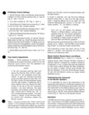
...Use only the Hi-Z or the Lo-Z input in an emergency with no damage to two-prong adapter. AUDIENCE MA6 MIXER BOARD STAGE • • • • • MA6 SPEAKERS (2) MICROPHONES IS) TYPICAL n • FIGURE 11 - AC Power Cord Remove the 120 VAC power ...shock. Typical Stage Setup FROM SPEAKER 12) JACKS os P E A MA6 A K MIXER K. E STANDARD SPEAKER CONNECTION NO. 1 FROM SPEAKER JACK (1) MA6 MIXER S P A K STANDARD SPEAKER CONNECTION NO. 2 • FIGURE 12 - DO NOT remove the grounding prong of the Mixer, marked "Speaker." Use only 8 "line" or "zip" cord ...
...Use only the Hi-Z or the Lo-Z input in an emergency with no damage to two-prong adapter. AUDIENCE MA6 MIXER BOARD STAGE • • • • • MA6 SPEAKERS (2) MICROPHONES IS) TYPICAL n • FIGURE 11 - AC Power Cord Remove the 120 VAC power ...shock. Typical Stage Setup FROM SPEAKER 12) JACKS os P E A MA6 A K MIXER K. E STANDARD SPEAKER CONNECTION NO. 1 FROM SPEAKER JACK (1) MA6 MIXER S P A K STANDARD SPEAKER CONNECTION NO. 2 • FIGURE 12 - DO NOT remove the grounding prong of the Mixer, marked "Speaker." Use only 8 "line" or "zip" cord ...
Owners Manual
Page 16
...a performing level, slowly turn up the Channel Level control until the speakers are used to adjust the tonal quality to suit the acoustics of the MA6 P.A. A performer with a quiet singing voice may require the Gain control to the Effects Receive jack (Fig. 9Item 4) and turning on the Monitor...Fig. 5-Item 3) for the monitors. NOTE: If the red overload warning light just above the Channel Gain control is "ahead" of the Mixer (Fig. 10 - Equalizers The MA6 has two 5-band graphic equalizers (Fig. 7 Item 1 and 2) one for the Main speakers and one of the instruments to their minimal ...
...a performing level, slowly turn up the Channel Level control until the speakers are used to adjust the tonal quality to suit the acoustics of the MA6 P.A. A performer with a quiet singing voice may require the Gain control to the Effects Receive jack (Fig. 9Item 4) and turning on the Monitor...Fig. 5-Item 3) for the monitors. NOTE: If the red overload warning light just above the Channel Gain control is "ahead" of the Mixer (Fig. 10 - Equalizers The MA6 has two 5-band graphic equalizers (Fig. 7 Item 1 and 2) one for the Main speakers and one of the instruments to their minimal ...

Owners Manual
Page 17
...5) should be used for the Monitor speakers. If the MA6 is a shelving-type control and acts like a horn. 1 kHz and 2 kHz (Peaking) - PRE AMP. Monitor Out Jack (Fig. 10 - MIXER USE Use of an Additional Mixer (Fig. 13) The Fender MA6 can also be used as the master unit, connect the... Main channel output of the device to the Master unit. Chaining Mixers Effects Send and Receive Jacks (Fig. 9 - If two different ...
...5) should be used for the Monitor speakers. If the MA6 is a shelving-type control and acts like a horn. 1 kHz and 2 kHz (Peaking) - PRE AMP. Monitor Out Jack (Fig. 10 - MIXER USE Use of an Additional Mixer (Fig. 13) The Fender MA6 can also be used as the master unit, connect the... Main channel output of the device to the Master unit. Chaining Mixers Effects Send and Receive Jacks (Fig. 9 - If two different ...

Owners Manual
Page 18
... 6 E A K E R U M S A P 6 E A K E R H POWER AMP 'PRE AMP "SPEAKER" OUT" OUT "MONITOR OUT" A' S U P X E I A L K 1 E A R R S AUXILIARY 'A'S • P X E I A L K I E A R R S MA6 MIXER POWER AMP MONITOR MONITOR • SPEAKER SPEAKER FIGURE 16 - If the MA6 is not already in parallel. To record the main channel signal, connect the tape recorder to the Effects Receive jack...should use . Item 1 and 2) or to the Pre-Amp Output jack (Fig. 10 Item 4). If the MA6 is 8 ohms and has two jacks in use high frequency speakers. Speaker Output Jacks and Speaker Systems The Power ...
... 6 E A K E R U M S A P 6 E A K E R H POWER AMP 'PRE AMP "SPEAKER" OUT" OUT "MONITOR OUT" A' S U P X E I A L K 1 E A R R S AUXILIARY 'A'S • P X E I A L K I E A R R S MA6 MIXER POWER AMP MONITOR MONITOR • SPEAKER SPEAKER FIGURE 16 - If the MA6 is not already in parallel. To record the main channel signal, connect the tape recorder to the Effects Receive jack...should use . Item 1 and 2) or to the Pre-Amp Output jack (Fig. 10 Item 4). If the MA6 is 8 ohms and has two jacks in use high frequency speakers. Speaker Output Jacks and Speaker Systems The Power ...

Owners Manual
Page 19
Bi-Amp Connections • **No S P E A K E R H TAPE RECORDER • 110--..111 S P "SPEAKER" E K "PRE AMP OUT" MA6 MIXER H -MONITOR OUT" POWER AMP MONITOR SPEAKER MONITOR SPEAKER FIGURE 18 - Tape Recording AMP OUT T J "MONITOR OUT" POWER AMP MONITOR SPEAKER MAS MIXER MONITOR SPEAKER FIGURE 17 - • SPEAKER (HIGH) SPEAKER (HIGH) SPEAKER (LOW) SPEAKER "POWER AMP IN" LOW ELECTRONIC CROSSOVER SPEAKER (LOW) HIGH POWER AMP PRE.
Bi-Amp Connections • **No S P E A K E R H TAPE RECORDER • 110--..111 S P "SPEAKER" E K "PRE AMP OUT" MA6 MIXER H -MONITOR OUT" POWER AMP MONITOR SPEAKER MONITOR SPEAKER FIGURE 18 - Tape Recording AMP OUT T J "MONITOR OUT" POWER AMP MONITOR SPEAKER MAS MIXER MONITOR SPEAKER FIGURE 17 - • SPEAKER (HIGH) SPEAKER (HIGH) SPEAKER (LOW) SPEAKER "POWER AMP IN" LOW ELECTRONIC CROSSOVER SPEAKER (LOW) HIGH POWER AMP PRE.