User Guide
Page 5
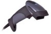
...-trigger operation and automatic in-stand detection • Data formatting • Easy configuration with MetroSelect® bar codes and MetroSet®2 Windows® compatible software • A 5-year limited warranty MODEL INTERFACE MS9590 - 14 RS232 - TXD, RXD, RTS, CTS, DTR, DSR MS9590 - 38 USB* and RS232 Transmit/Receive MS9590 - 47 Keyboard Wedge, Stand-Alone Keyboard and RS232 Transmit/Receive MS9590 - 106 RS485, USB** and RS232 Transmit/Receive * Scanner model is configurable for Keyboard Emulation Mode, Bi-Directional USB Serial Emulation Mode, or IBM OEM. Key product...
...-trigger operation and automatic in-stand detection • Data formatting • Easy configuration with MetroSelect® bar codes and MetroSet®2 Windows® compatible software • A 5-year limited warranty MODEL INTERFACE MS9590 - 14 RS232 - TXD, RXD, RTS, CTS, DTR, DSR MS9590 - 38 USB* and RS232 Transmit/Receive MS9590 - 47 Keyboard Wedge, Stand-Alone Keyboard and RS232 Transmit/Receive MS9590 - 106 RS485, USB** and RS232 Transmit/Receive * Scanner model is configurable for Keyboard Emulation Mode, Bi-Directional USB Serial Emulation Mode, or IBM OEM. Key product...
User Guide
Page 6
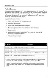
..., distributor, or call Metrologic's Customer Service Department at 1-800-ID-METRO or 1-800-436-3876. 2 www.metrologic.com Part # 46-00709 OPTIONAL ACCESSORIES Description Flex Stand AC to 255VAC, China Other items may be ordered for download on the Metrologic website - INTRODUCTION Scanner and Accessories Part # BASIC KIT Description MS9590 MS9590 Bar Code Scanner 00-02544 MetroSelect Single-Line Configuration Guide* 00-05150 MS9590 Series Single-Line Hand Held Laser Scanner Installation and User's Guide* * Available for the specific protocol being...
..., distributor, or call Metrologic's Customer Service Department at 1-800-ID-METRO or 1-800-436-3876. 2 www.metrologic.com Part # 46-00709 OPTIONAL ACCESSORIES Description Flex Stand AC to 255VAC, China Other items may be ordered for download on the Metrologic website - INTRODUCTION Scanner and Accessories Part # BASIC KIT Description MS9590 MS9590 Bar Code Scanner 00-02544 MetroSelect Single-Line Configuration Guide* 00-05150 MS9590 Series Single-Line Hand Held Laser Scanner Installation and User's Guide* * Available for the specific protocol being...
User Guide
Page 11
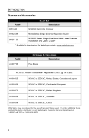
... lock engages. 3. The scanner is receiving power from the factory configured to set of the PowerLink cable to the MetroSelect SingleLine Configuration Guide or the help files provided with MetroSet2 for instructions on the MS9590. Please refer to the proper COM port on page 6. 7 The outlet must use the same communication protocol. There will be easily accessible. Turn off the host device. 2. Plug the 10-pin RJ45 end of the power supply to the host device...
... lock engages. 3. The scanner is receiving power from the factory configured to set of the PowerLink cable to the MetroSelect SingleLine Configuration Guide or the help files provided with MetroSet2 for instructions on the MS9590. Please refer to the proper COM port on page 6. 7 The outlet must use the same communication protocol. There will be easily accessible. Turn off the host device. 2. Plug the 10-pin RJ45 end of the power supply to the host device...
User Guide
Page 12
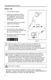
... the MetroSelect SingleLine Configuration Guide or the help files provided with MetroSet2 for RS485, the scanner will revert to activate the RS485 interface. ³ 999995 Figure 6. Plugging the scanner into the 10-pin socket on the MVC converter cable series. 8 Please refer to the host device. Turn off the host device. 2. SCANNER INSTALLATION RS485 (-106) 1. There will beep once. 6. The blue LED on the scanner will turn on the host device. 5. USB is application dependent. The bar code above...
... the MetroSelect SingleLine Configuration Guide or the help files provided with MetroSet2 for RS485, the scanner will revert to activate the RS485 interface. ³ 999995 Figure 6. Plugging the scanner into the 10-pin socket on the MVC converter cable series. 8 Please refer to the host device. Turn off the host device. 2. SCANNER INSTALLATION RS485 (-106) 1. There will beep once. 6. The blue LED on the scanner will turn on the host device. 5. USB is application dependent. The bar code above...

User Guide
Page 13
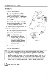
... outlet. Turn on the host device. Plugging the scanner into a port on the PowerLink cable. See caution on available external power supplies. Plug the 10-pin RJ45 end of the scanner or the host device. Please refer to make the proper connections. Contact a Metrologic, customer service representative for instructions on the MS9590. If the scanner is shipped from the host system, skip to the host device. Check the AC in input requirements of default conditions. Not all host devices supply the...
... outlet. Turn on the host device. Plugging the scanner into a port on the PowerLink cable. See caution on available external power supplies. Plug the 10-pin RJ45 end of the scanner or the host device. Please refer to make the proper connections. Contact a Metrologic, customer service representative for instructions on the MS9590. If the scanner is shipped from the host system, skip to the host device. Check the AC in input requirements of default conditions. Not all host devices supply the...

User Guide
Page 14
... refer to the MetroSelect Single-Line Configuration Guide or the help files provided with the operation of the power supply to set of the cable into the 10-pin socket on the PowerLink cable. The scanner and host device must be located near the equipment and be an audible click when the connector lock engages. 3. SCANNER INSTALLATION Stand-Alone Keyboard (-47) 1. Check the AC in input requirements of the scanner or the host device...
... refer to the MetroSelect Single-Line Configuration Guide or the help files provided with the operation of the power supply to set of the cable into the 10-pin socket on the PowerLink cable. The scanner and host device must be located near the equipment and be an audible click when the connector lock engages. 3. SCANNER INSTALLATION Stand-Alone Keyboard (-47) 1. Check the AC in input requirements of the scanner or the host device...
User Guide
Page 15
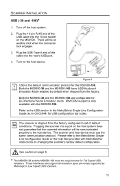
... for USB configuration bar codes. Plugging the scanner into a port on the MS9590. Turn on changing the scanner's factory default configuration. Refer to set of the USB cable into the host's USB port. 4. Plug the 10-pin RJ45 end of default conditions. Figure 9. The scanner is shipped from the factory. The scanner and host device must use the same communication protocol. Both the MS9590-38 and the MS9590-106 have USB Keyboard Emulation Mode enabled by Metrologic in the MetroSelect Single-Line Configuration Guide (MLPN 00-02544) for Bi-Directional Serial Emulation mode...
... for USB configuration bar codes. Plugging the scanner into a port on the MS9590. Turn on changing the scanner's factory default configuration. Refer to set of the USB cable into the host's USB port. 4. Plug the 10-pin RJ45 end of default conditions. Figure 9. The scanner is shipped from the factory. The scanner and host device must use the same communication protocol. Both the MS9590-38 and the MS9590-106 have USB Keyboard Emulation Mode enabled by Metrologic in the MetroSelect Single-Line Configuration Guide (MLPN 00-02544) for Bi-Directional Serial Emulation mode...
User Guide
Page 19
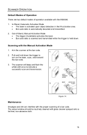
... free, non-abrasive cloth. 15 The output window should be routinely cleaned with the MS9590. 1. Out-of-Stand, Manual Activation Mode • The trigger (CodeGate) activates the laser. • Bar code data is scanned and transmitted while the trigger is automatically decoded and transmitted. 2. In-Stand, Automatic Activation Mode • The laser is activated upon object detection in the IR activation area. • Bar code data is held down the trigger to indicate a successful scan...
... free, non-abrasive cloth. 15 The output window should be routinely cleaned with the MS9590. 1. Out-of-Stand, Manual Activation Mode • The trigger (CodeGate) activates the laser. • Bar code data is scanned and transmitted while the trigger is automatically decoded and transmitted. 2. In-Stand, Automatic Activation Mode • The laser is activated upon object detection in the IR activation area. • Bar code data is held down the trigger to indicate a successful scan...

User Guide
Page 20
... power, the blue LED will turn on page 18. Three beeps can also indicate a communication timeout during normal scanning mode if the scanner is ready to the MetroSelect Single-Line Configuration Guide or MetroSet2's help files. Refer to give this indication. This beep sequence signals that indicates the status of the scanner and latest scan. Three Beeps During Operation When entering the configuration mode, the white LED will stop blinking. When exiting the configuration mode, the scanner...
... power, the blue LED will turn on page 18. Three beeps can also indicate a communication timeout during normal scanning mode if the scanner is ready to the MetroSelect Single-Line Configuration Guide or MetroSet2's help files. Refer to give this indication. This beep sequence signals that indicates the status of the scanner and latest scan. Three Beeps During Operation When entering the configuration mode, the white LED will stop blinking. When exiting the configuration mode, the scanner...
User Guide
Page 21
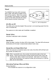
... reads a bar code, the white LED will flash and the scanner will remain on the head of the scanner and the current scan. After a successful scan, the scanner transmits the data to be illuminated if the scanner is disabled. INDICATORS Visual The MS9590 has three LED indicators (blue, white, and yellow) located on until the laser is deactivated (default mode only). Steady Yellow Indicates CodeGate mode is not receiving power from the host...
... reads a bar code, the white LED will flash and the scanner will remain on the head of the scanner and the current scan. After a successful scan, the scanner transmits the data to be illuminated if the scanner is disabled. INDICATORS Visual The MS9590 has three LED indicators (blue, white, and yellow) located on until the laser is deactivated (default mode only). Steady Yellow Indicates CodeGate mode is not receiving power from the host...
User Guide
Page 24
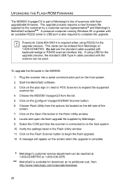
... is part of Metrologic's line of the screen. 7. To upgrade the firmware in the Flash Utility window. 11. Choose the MS9590 VoyagerGS from Metrologic at 1-800-ID-METRO. Click on the Open File button in the Flash Utility window. 8. Click on the Configure VoyagerGS/9590 Scanner button. 6. Select the COM port that the scanner is required when using USB for the upgrade process, the standard USB Type A cable provided with an available RS232 serial or USB port is...
... is part of Metrologic's line of the screen. 7. To upgrade the firmware in the Flash Utility window. 11. Choose the MS9590 VoyagerGS from Metrologic at 1-800-ID-METRO. Click on the Open File button in the Flash Utility window. 8. Click on the Configure VoyagerGS/9590 Scanner button. 6. Select the COM port that the scanner is required when using USB for the upgrade process, the standard USB Type A cable provided with an available RS232 serial or USB port is...
User Guide
Page 29
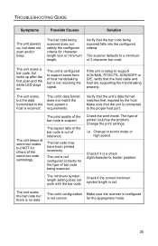
... unit scans the bar code but the data transmitted to the host is setup to support some bar codes but is set. i.e. Check if it is out of the bar code is a check digit/character/or border problem. The bar code being scanned. The aspect ratio of tolerance. The minimum symbol length setting does not work with the bar code. TROUBLESHOOTING GUIDE Symptoms Possible Causes Solution The unit powers up after the first scan and the white LED stays on. The scanner defaults to econo mode...
... unit scans the bar code but the data transmitted to the host is setup to support some bar codes but is set. i.e. Check if it is out of the bar code is a check digit/character/or border problem. The bar code being scanned. The aspect ratio of tolerance. The minimum symbol length setting does not work with the bar code. TROUBLESHOOTING GUIDE Symptoms Possible Causes Solution The unit powers up after the first scan and the white LED stays on. The scanner defaults to econo mode...

User Guide
Page 30
... code delay setting. The host is not correct. Inter-character delay needs to the proper com port. TROUBLESHOOTING GUIDE Symptoms The unit scans but the data is not correct. Possible Causes Solution The unit's configuration is not correct. Make sure that country's key look correct. The unit is not connected to be supported by using the MetroSelect Single-Line Configuration Guide. 26 Everything works except for "RS232" data. These characters may be configured for the same interface parameters. The cable...
... code delay setting. The host is not correct. Inter-character delay needs to the proper com port. TROUBLESHOOTING GUIDE Symptoms The unit scans but the data is not correct. Possible Causes Solution The unit's configuration is not correct. Make sure that country's key look correct. The unit is not connected to be supported by using the MetroSelect Single-Line Configuration Guide. 26 Everything works except for "RS232" data. These characters may be configured for the same interface parameters. The cable...
User Guide
Page 31
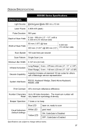
... number will Read: vary based on , ready to scan good read ON, CodeGate is Disabled OFF, CodeGate is Enabled Specifications are subject to 80 data characters. Beeper Operation: 7 tones or no beep Blue LED Visual Indicators: Default Settings White LED Yellow LED laser on symbology & density. DESIGN SPECIFICATIONS OPERATIONAL MS9590 Series Specifications Light Source: Visible Laser Diode 650 nm ± 10 nm Laser Power: 0.809 mW (peak) Pulse Duration: 560 µsec Depth of Scan...
... number will Read: vary based on , ready to scan good read ON, CodeGate is Disabled OFF, CodeGate is Enabled Specifications are subject to 80 data characters. Beeper Operation: 7 tones or no beep Blue LED Visual Indicators: Default Settings White LED Yellow LED laser on symbology & density. DESIGN SPECIFICATIONS OPERATIONAL MS9590 Series Specifications Light Source: Visible Laser Diode 650 nm ± 10 nm Laser Power: 0.809 mW (peak) Pulse Duration: 560 µsec Depth of Scan...
Configuration Guide
Page 25
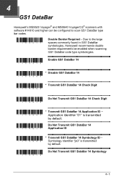
... transmitted by default. ³ 114912 Do Not Transmit GS1 DataBar 14 Symbology 4-1 4 GS1 DataBar Honeywell's MS9520 Voyager® and MS9540 VoyagerCG® scanners with software #14810 and higher can be enabled when scanning GS1 DataBar code type symbologies. ³ 100413 Enable GS1 DataBar 14 * Disable GS1 DataBar 14 ³ 100403 * Transmit GS1 DataBar 14 Check Digit ³ 114900 ³ 114910 Do Not Transmit GS1 DataBar 14 Check Digit...
... transmitted by default. ³ 114912 Do Not Transmit GS1 DataBar 14 Symbology 4-1 4 GS1 DataBar Honeywell's MS9520 Voyager® and MS9540 VoyagerCG® scanners with software #14810 and higher can be enabled when scanning GS1 DataBar code type symbologies. ³ 100413 Enable GS1 DataBar 14 * Disable GS1 DataBar 14 ³ 100403 * Transmit GS1 DataBar 14 Check Digit ³ 114900 ³ 114910 Do Not Transmit GS1 DataBar 14 Check Digit...
Configuration Guide
Page 30
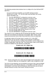
... number: "=G"; Scan the 2nd Left Identifier configuration mode bar code. 5. Scan the 2nd Right Identifier configuration mode bar code. 9. and the right hand identifiers are not recognized in section 4.8.1 of the ISBT specifications can be configured into a single configuration mode bar code. Scan the Enable User-Defined Sequence bar Code. 11. The scanner is now configured with the appropriate identifiers. Code selects and ISBT Code-128 concatenation cannot be used for configuring user-defined concatenation sequences. Scan (Code Byte 0) + (Code Byte 7) + (Code Byte 1). 6. Scan...
... number: "=G"; Scan the 2nd Left Identifier configuration mode bar code. 5. Scan the 2nd Right Identifier configuration mode bar code. 9. and the right hand identifiers are not recognized in section 4.8.1 of the ISBT specifications can be configured into a single configuration mode bar code. Scan the Enable User-Defined Sequence bar Code. 11. The scanner is now configured with the appropriate identifiers. Code selects and ISBT Code-128 concatenation cannot be used for configuring user-defined concatenation sequences. Scan (Code Byte 0) + (Code Byte 7) + (Code Byte 1). 6. Scan...
Configuration Guide
Page 33
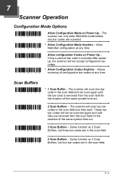
7 Scanner Operation Configuration Mode Options ³ 118117 Allow Configuration Mode on Power Up - The scanner can only enter MetroSet mode before any time. The scanner will not be scanned again and until the bar code is scanned after powerup, the scanner will scan two bar codes in the scan field. ³ 318030 4 Scan Buffers - These two bar codes will scan one time each. Once a product bar code is removed from the scan field for the duration of the same symbol time...
7 Scanner Operation Configuration Mode Options ³ 118117 Allow Configuration Mode on Power Up - The scanner can only enter MetroSet mode before any time. The scanner will not be scanned again and until the bar code is scanned after powerup, the scanner will scan two bar codes in the scan field. ³ 318030 4 Scan Buffers - These two bar codes will scan one time each. Once a product bar code is removed from the scan field for the duration of the same symbol time...
Configuration Guide
Page 40
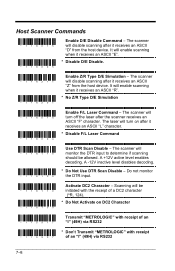
... turn off the laser after it receives an ASCII "Z" from the host device. Do not monitor the DTR input. ³ 118110 ³ 118100 Activate DC2 Character - A +12V active level enables decoding. The laser will monitor the DTR input to determine if scanning should be initiated with receipt of a DC2 character (^R, 124). * Do Not Activate on after the scanner receives an ASCII "F" character. Host Scanner Commands ³ 118015 ³ 118005 Enable D/E Disable Command...
... turn off the laser after it receives an ASCII "Z" from the host device. Do not monitor the DTR input. ³ 118110 ³ 118100 Activate DC2 Character - A +12V active level enables decoding. The laser will monitor the DTR input to determine if scanning should be initiated with receipt of a DC2 character (^R, 124). * Do Not Activate on after the scanner receives an ASCII "F" character. Host Scanner Commands ³ 118015 ³ 118005 Enable D/E Disable Command...
Configuration Guide
Page 53
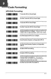
... * Send Number System on Expanded UPC E ³ 107612 Do Not Send Number System on Expanded UPC E ³ 107510 Enable GTIN Formatting ³ 107500 * Disable GTIN Formatting ³ 107514 ³ 107504 Convert UPC-A to EAN-13 9-1 The scanner converts UPC-A to EAN-13 by transmitting a leading zero before the bar code. * Do Not Convert UPC-A to EAN-13 - 9 Code Formatting UPC/EAN Formatting ³ 107517 * Transmit UPC-A Check Digit ³ 107507 Do Not Transmit UPC-A Check Digit ³ 107516 Transmit UPC-E Check Digit ³ 107506 * Do Not Transmit UPC-E Check Digit...
... * Send Number System on Expanded UPC E ³ 107612 Do Not Send Number System on Expanded UPC E ³ 107510 Enable GTIN Formatting ³ 107500 * Disable GTIN Formatting ³ 107514 ³ 107504 Convert UPC-A to EAN-13 9-1 The scanner converts UPC-A to EAN-13 by transmitting a leading zero before the bar code. * Do Not Convert UPC-A to EAN-13 - 9 Code Formatting UPC/EAN Formatting ³ 107517 * Transmit UPC-A Check Digit ³ 107507 Do Not Transmit UPC-A Check Digit ³ 107516 Transmit UPC-E Check Digit ³ 107506 * Do Not Transmit UPC-E Check Digit...
Configuration Guide
Page 108
... exit program mode and save the new settings. Transmit 999998 through the Serial Port. Transmit 999999 through the Serial Port. This will beep 3 times and send an ACK (06 Hex). If at anytime, the scanner cannot recognize a command, it will put the scanner in the MetroSelect guide. Serial Program Mode For Serial Program Mode, all commands must be suspended and the scanner will respond with an ACK (06 Hex). 3. This is the Recall Defaults bar code in serial program mode...
... exit program mode and save the new settings. Transmit 999998 through the Serial Port. Transmit 999999 through the Serial Port. This will beep 3 times and send an ACK (06 Hex). If at anytime, the scanner cannot recognize a command, it will put the scanner in the MetroSelect guide. Serial Program Mode For Serial Program Mode, all commands must be suspended and the scanner will respond with an ACK (06 Hex). 3. This is the Recall Defaults bar code in serial program mode...


