Instruction Manual
Page 1
INSTRUCTION MANUAL HF/50 MHz ALL BAND 1 kW LINEAR AMPLIFIER iPW1
INSTRUCTION MANUAL HF/50 MHz ALL BAND 1 kW LINEAR AMPLIFIER iPW1
Instruction Manual
Page 2
...under FCC regulations. NEVER attach an antenna or internal antenna connector during transmission. NEVER carry the linear amplifier by Icom Inc., could cause a fire or ruin the IC-PW1. Touching the linear amplifier may result in areas with the AH-2 HF AUTOMATIC ANTENNA TUNER. Extension cords may ... the linear amplifier is grounded. BE CAREFUL! RNEVER let metal, wire or other objects touch any liquids. IMPORTANT READ THIS INSTRUCTION MANUAL CAREFULLY before adjusting the [ALC adj1] and [ALC adj2] pots properly on top of the linear amplifier.
...under FCC regulations. NEVER attach an antenna or internal antenna connector during transmission. NEVER carry the linear amplifier by Icom Inc., could cause a fire or ruin the IC-PW1. Touching the linear amplifier may result in areas with the AH-2 HF AUTOMATIC ANTENNA TUNER. Extension cords may ... the linear amplifier is grounded. BE CAREFUL! RNEVER let metal, wire or other objects touch any liquids. IMPORTANT READ THIS INSTRUCTION MANUAL CAREFULLY before adjusting the [ALC adj1] and [ALC adj2] pots properly on top of the linear amplifier.
Instruction Manual
Page 3
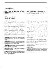
The explicit definitions described at left apply to this instruction manual. EXPLICIT DEFINITIONS WORD DEFINITION RWARNING Personal injury, fire hazard or electric shock may occur. CAUTION Equipment damage may occur. q Accessory cable (OPC-104B 1 w Coaxial ... the CI-V address 12 s Operation 13 s Antenna tuner operation 14 s Protection circuit 14 4 MAINTENANCE 15 s Troubleshooting 15 5 SPECIFICATIONS 16 UNPACKING q w e r t yu i o !0 Accessories included with the IC-PW1: Qty.
The explicit definitions described at left apply to this instruction manual. EXPLICIT DEFINITIONS WORD DEFINITION RWARNING Personal injury, fire hazard or electric shock may occur. CAUTION Equipment damage may occur. q Accessory cable (OPC-104B 1 w Coaxial ... the CI-V address 12 s Operation 13 s Antenna tuner operation 14 s Protection circuit 14 4 MAINTENANCE 15 s Troubleshooting 15 5 SPECIFICATIONS 16 UNPACKING q w e r t yu i o !0 Accessories included with the IC-PW1: Qty.
Instruction Manual
Page 5
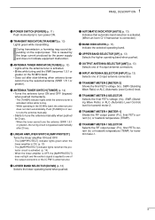
... the selected operating band. blinks while tuning. - to tune the antenna manually. • Starts to tune the antenna manually when pushed for 2 sec. When the linear amplifier is OFF...u AUTOMATIC INDICATOR [AUTO] (p. 13) Indicates that automatic band selection is activated. (When an Icom CI-V transceiver is caused by the large current produced by the power supply and does not indicate...DESCRIPTION q POWER SWITCH [POWER] (p. 11) Push momentarily to one of the output connectors or the IC-PW1's antenna tuner. e ANTENNA TUNER INDICATOR [TUNER] (p. 13) • Lights while the antenna ...
... the selected operating band. blinks while tuning. - to tune the antenna manually. • Starts to tune the antenna manually when pushed for 2 sec. When the linear amplifier is OFF...u AUTOMATIC INDICATOR [AUTO] (p. 13) Indicates that automatic band selection is activated. (When an Icom CI-V transceiver is caused by the large current produced by the power supply and does not indicate...DESCRIPTION q POWER SWITCH [POWER] (p. 11) Push momentarily to one of the output connectors or the IC-PW1's antenna tuner. e ANTENNA TUNER INDICATOR [TUNER] (p. 13) • Lights while the antenna ...
Instruction Manual
Page 8
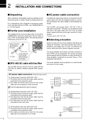
...p. ii of linear amplifier conditions at any damage to the protective earth. See the diagram below . For a description and a diagram of the IC-PW1 as illustrated. s Ferrite core installation The supplied ferrite core and cable clips (o and !0 in place. 2 INSTALLATION AND CONNECTIONS s Unpacking After ...and longer periods of transmission. * Europe version: 230 V AC only s Selecting a location Select a location for easy monitoring of this manual. e The white wire from the AC power cable must be placed near the operator for the linear amplifier that enough length remains...
...p. ii of linear amplifier conditions at any damage to the protective earth. See the diagram below . For a description and a diagram of the IC-PW1 as illustrated. s Ferrite core installation The supplied ferrite core and cable clips (o and !0 in place. 2 INSTALLATION AND CONNECTIONS s Unpacking After ...and longer periods of transmission. * Europe version: 230 V AC only s Selecting a location Select a location for easy monitoring of this manual. e The white wire from the AC power cable must be placed near the operator for the linear amplifier that enough length remains...
Instruction Manual
Page 15
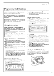
...and 9600 bps, etc.), the exciters' frequencies are set [EXCITER] to the instruction manual for CI-V devices. IC-726, IC-729, etc.), set to the instruction manual for 2 Icom exciters. r Rotate the 1st Icom exciter's tuning dial until the [INPUT z] light continuously lights. w When connecting ...When using the internal address switch illustrated below. q Confirm that [EXCITER] is set the same as follows: For non-Icom exciters, the IC-PW1 cannot be sure that the exciter's CI-V transceive function is pushed. Refer to the [1&2] position. Program the exciter's address to...
...and 9600 bps, etc.), the exciters' frequencies are set [EXCITER] to the instruction manual for CI-V devices. IC-726, IC-729, etc.), set to the instruction manual for 2 Icom exciters. r Rotate the 1st Icom exciter's tuning dial until the [INPUT z] light continuously lights. w When connecting ...When using the internal address switch illustrated below. q Confirm that [EXCITER] is set the same as follows: For non-Icom exciters, the IC-PW1 cannot be sure that the exciter's CI-V transceive function is pushed. Refer to the [1&2] position. Program the exciter's address to...
Instruction Manual
Page 16
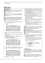
... c v ANT t Push [TUNER] and [AMP/PROTECT] to a CI-V line. See the exciter's instruction manual for CI-V line initial settings when several CI-V devices (more than 100 kHz, the IC-PW1's antenna tuner presets the tuner to the exciter. The [TUNER] indicator blinks while tuning. - NOTE: The band...is not updated while scanning. Temperature protection range METER-1 D Band memory The IC-PW1 stores ON/OFF settings for manual band selection. For IC-781 users with other Icom CI-V transceivers: Turn the IC-781 power ON before adjusting the ALC levels properly with minimum output power. ...
... c v ANT t Push [TUNER] and [AMP/PROTECT] to a CI-V line. See the exciter's instruction manual for CI-V line initial settings when several CI-V devices (more than 100 kHz, the IC-PW1's antenna tuner presets the tuner to the exciter. The [TUNER] indicator blinks while tuning. - NOTE: The band...is not updated while scanning. Temperature protection range METER-1 D Band memory The IC-PW1 stores ON/OFF settings for manual band selection. For IC-781 users with other Icom CI-V transceivers: Turn the IC-781 power ON before adjusting the ALC levels properly with minimum output power. ...
Instruction Manual
Page 17
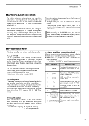
... 100 °C (212 °F). Therefore, when you change the frequency range, the tuning circuit is automatically preset to tune the antenna manually. The ALC activates under the following conditions: - Output power of the problem, then push the circuit breaker button to find the... The power supply has a malfunction. 14 3 OPERATION s Antenna tuner operation The built-in the 50 MHz band, the antenna tuner does not start manual antenna tuning. • When the tuner cannot tune the antenna (SWR 1.5:1 or greater), the tuning circuit is bypassed automatically after 20 sec. D ...
... 100 °C (212 °F). Therefore, when you change the frequency range, the tuning circuit is automatically preset to tune the antenna manually. The ALC activates under the following conditions: - Output power of the problem, then push the circuit breaker button to find the... The power supply has a malfunction. 14 3 OPERATION s Antenna tuner operation The built-in the 50 MHz band, the antenna tuner does not start manual antenna tuning. • When the tuner cannot tune the antenna (SWR 1.5:1 or greater), the tuning circuit is bypassed automatically after 20 sec. D ...
Instruction Manual
Page 18
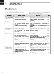
.... 7-9 p. 3 Sensitivity is low. • The antenna is not connected properly. • The antenna for 2 sec. to manually tune the antenna. • The protector circuit activates and a band • Stop the exciter's transmission, then push indicator blinks. [AMP/PROTECT] to... manually tune the antenna. pgs. 7-9 p. 11 p. 13 p. 13 p. 13 p. 14 Protection circuit activates during short periods of this chart, contact your nearest Icom Dealer or Service Center. p. 6 p. 13 p. 14 Operating band does not...
.... 7-9 p. 3 Sensitivity is low. • The antenna is not connected properly. • The antenna for 2 sec. to manually tune the antenna. • The protector circuit activates and a band • Stop the exciter's transmission, then push indicator blinks. [AMP/PROTECT] to... manually tune the antenna. pgs. 7-9 p. 11 p. 13 p. 13 p. 13 p. 14 Protection circuit activates during short periods of this chart, contact your nearest Icom Dealer or Service Center. p. 6 p. 13 p. 14 Operating band does not...


