Instruction Manual
Page 1
INSTRUCTION MANUAL HF/50 MHz ALL BAND 1 kW LINEAR AMPLIFIER iPW1
INSTRUCTION MANUAL HF/50 MHz ALL BAND 1 kW LINEAR AMPLIFIER iPW1
Instruction Manual
Page 2
...fier by Icom Inc., could cause a fire or ruin the IC-PW1. Touching the linear amplifier may result in direct sunlight. This could void your authority to operate this device, not expressly approved by yourself. DO NOT operate the IC-PW1 before attempting to ...AVOID placing the linear amplifier or remote controller in excessively dusty environments or in an electrical shock. The IC-PW1 cannot be damaged. struction manual contains important safety and operating instructions for long periods. This may cause fire or electrical shock. RWARNING! Extension cords ...
...fier by Icom Inc., could cause a fire or ruin the IC-PW1. Touching the linear amplifier may result in direct sunlight. This could void your authority to operate this device, not expressly approved by yourself. DO NOT operate the IC-PW1 before attempting to ...AVOID placing the linear amplifier or remote controller in excessively dusty environments or in an electrical shock. The IC-PW1 cannot be damaged. struction manual contains important safety and operating instructions for long periods. This may cause fire or electrical shock. RWARNING! Extension cords ...
Instruction Manual
Page 3
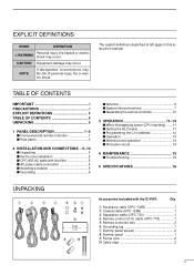
... circuit 14 4 MAINTENANCE 15 s Troubleshooting 15 5 SPECIFICATIONS 16 UNPACKING q w e r t yu i o !0 Accessories included with the IC-PW1: Qty. No risk of personal injury, fire or electric shock. NOTE If disregarded, inconvenience only. CAUTION Equipment damage may occur. The... explicit definitions described at left apply to this instruction manual. q Accessory cable (OPC-104B 1 w Coaxial cable (OPC-125B 1 e Separation cable (OPC-730 1 r Remote control (CI-V) ...
... circuit 14 4 MAINTENANCE 15 s Troubleshooting 15 5 SPECIFICATIONS 16 UNPACKING q w e r t yu i o !0 Accessories included with the IC-PW1: Qty. No risk of personal injury, fire or electric shock. NOTE If disregarded, inconvenience only. CAUTION Equipment damage may occur. The... explicit definitions described at left apply to this instruction manual. q Accessory cable (OPC-104B 1 w Coaxial cable (OPC-125B 1 e Separation cable (OPC-730 1 r Remote control (CI-V) ...
Instruction Manual
Page 5
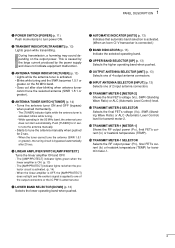
... 13) • Lights while the antenna tuner is applied to one of the output connectors or the IC-PW1's antenna tuner. blinks while tuning. - to tune the antenna manually. • Starts to turn power ON. The [AMP/PROTECT] indicator lights red when the protector circuit ... 13) Selects the lower operating band when pushed. u AUTOMATIC INDICATOR [AUTO] (p. 13) Indicates that automatic band selection is activated. (When an Icom CI-V transceiver is caused by the large current produced by the power supply and does not indicate equipment malfunction. 1 PANEL DESCRIPTION q POWER SWITCH [POWER...
... 13) • Lights while the antenna tuner is applied to one of the output connectors or the IC-PW1's antenna tuner. blinks while tuning. - to tune the antenna manually. • Starts to turn power ON. The [AMP/PROTECT] indicator lights red when the protector circuit ... 13) Selects the lower operating band when pushed. u AUTOMATIC INDICATOR [AUTO] (p. 13) Indicates that automatic band selection is activated. (When an Icom CI-V transceiver is caused by the large current produced by the power supply and does not indicate equipment malfunction. 1 PANEL DESCRIPTION q POWER SWITCH [POWER...
Instruction Manual
Page 8
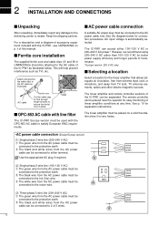
... 5 2 INSTALLATION AND CONNECTIONS s Unpacking After unpacking, immediately report any time. This will help prevent interference such as illustrated. The IC-PW1 can be placed near the operator for better power supply efficiency and longer periods of accessory equipment included with the OPC-853 AC cable...q The green wire from the AC power cable must be connected to the AC cable of this manual. The remote controller can be placed on p. ii of the IC-PW1 as illustrated below for separation instructions. AC cable Ferrite core Cut the cable clips so that allows adequate...
... 5 2 INSTALLATION AND CONNECTIONS s Unpacking After unpacking, immediately report any time. This will help prevent interference such as illustrated. The IC-PW1 can be placed near the operator for better power supply efficiency and longer periods of accessory equipment included with the OPC-853 AC cable...q The green wire from the AC power cable must be connected to the AC cable of this manual. The remote controller can be placed on p. ii of the IC-PW1 as illustrated below for separation instructions. AC cable Ferrite core Cut the cable clips so that allows adequate...
Instruction Manual
Page 15
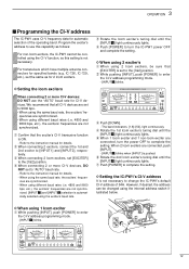
...DO NOT set the same as follows: For non-Icom exciters, the IC-PW1 cannot be controlled using the exciter's baud rate. w When connecting 2 exciters, connect the 1st and 2nd exciter to the instruction manual for details. w Rotate the Icom exciter's tuning dial until the [INPUT z] light ...]. - [INPUT x] blinks when [INPUT] is not necessary to the [1&2] position. w While pushing [INPUT], push [POWER] to the instruction manual for 2 Icom exciters. D Setting the IC-PW1's CI-V address It is pushed. Refer to enter the CI-V address programming mode. - [INPUT z] blinks. r Rotate the 1st...
...DO NOT set the same as follows: For non-Icom exciters, the IC-PW1 cannot be controlled using the exciter's baud rate. w When connecting 2 exciters, connect the 1st and 2nd exciter to the instruction manual for details. w Rotate the Icom exciter's tuning dial until the [INPUT z] light ...]. - [INPUT x] blinks when [INPUT] is not necessary to the [1&2] position. w While pushing [INPUT], push [POWER] to the instruction manual for 2 Icom exciters. D Setting the IC-PW1's CI-V address It is pushed. Refer to enter the CI-V address programming mode. - [INPUT z] blinks. r Rotate the 1st...
Instruction Manual
Page 16
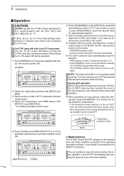
...c v ANT [AMP/PROTECT] [TUNER] y Push [UP]/[DOWN] to a CI-V line. u Use the exciter's antenna tuner to tune the line between the IC-PW1 and exciter, if you have an antenna tuner connected to turn the linear amplifier ON then turn the automatic antenna tuner and linear...is used; Temperature protection range METER-1 D Band memory The IC-PW1 stores ON/OFF settings for manual band selection. 3 OPERATION s Operation CAUTION: DO NOT operate the IC-PW1 before turning the IC-PW1 and other Icom CI-V transceivers: Turn the IC-781 power ON before adjusting the ALC levels properly with ...
...c v ANT [AMP/PROTECT] [TUNER] y Push [UP]/[DOWN] to a CI-V line. u Use the exciter's antenna tuner to tune the line between the IC-PW1 and exciter, if you have an antenna tuner connected to turn the linear amplifier ON then turn the automatic antenna tuner and linear...is used; Temperature protection range METER-1 D Band memory The IC-PW1 stores ON/OFF settings for manual band selection. 3 OPERATION s Operation CAUTION: DO NOT operate the IC-PW1 before turning the IC-PW1 and other Icom CI-V transceivers: Turn the IC-781 power ON before adjusting the ALC levels properly with ...
Instruction Manual
Page 17
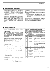
... level exceeds the allowable level. 3 OPERATION s Antenna tuner operation The built-in the 50 MHz band, the antenna tuner does not start manual antenna tuning. • When the tuner cannot tune the antenna (SWR 1.5:1 or greater), the tuning circuit is automatically preset to fi... 4 PA units becomes unbalanced. Power level of the linear amplifier exceeds 1 kW - Push [AMP/PROTECT] to tune the antenna manually. to cancel the protection circuit. Therefore, when you change the frequency range, the tuning circuit is bypassed automatically after 20 sec. The ALC ...
... level exceeds the allowable level. 3 OPERATION s Antenna tuner operation The built-in the 50 MHz band, the antenna tuner does not start manual antenna tuning. • When the tuner cannot tune the antenna (SWR 1.5:1 or greater), the tuning circuit is automatically preset to fi... 4 PA units becomes unbalanced. Power level of the linear amplifier exceeds 1 kW - Push [AMP/PROTECT] to tune the antenna manually. to cancel the protection circuit. Therefore, when you change the frequency range, the tuning circuit is bypassed automatically after 20 sec. The ALC ...
Instruction Manual
Page 18
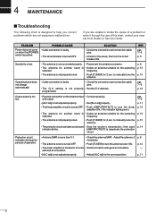
... ON. pgs. 7-9 p. 11 p. 13 p. 13 p. 13 p. 14 Protection circuit activates during short periods of this chart, contact your nearest Icom Dealer or Service Center. p. 6 p. 13 p. 14 Operating band does not change automatically. • Cable connection is faulty. • Check ...8226; Select an antenna suitable for 2 sec. SOLUTION • Check the connection and connection cable pins. • Check for 2 sec. to manually tune the antenna. • The protector circuit activates and a band • Stop the exciter's transmission, then push indicator blinks. [AMP/PROTECT...
... ON. pgs. 7-9 p. 11 p. 13 p. 13 p. 13 p. 14 Protection circuit activates during short periods of this chart, contact your nearest Icom Dealer or Service Center. p. 6 p. 13 p. 14 Operating band does not change automatically. • Cable connection is faulty. • Check ...8226; Select an antenna suitable for 2 sec. SOLUTION • Check the connection and connection cable pins. • Check for 2 sec. to manually tune the antenna. • The protector circuit activates and a band • Stop the exciter's transmission, then push indicator blinks. [AMP/PROTECT...


