
Instruction Manual
Page 1
INSTRUCTION MANUAL DIGITAL TRANSCEIVER ID-1 DIGITAL TRANSCEIVER ID-1 MIC TD/RD PWR TX/RX POWER
INSTRUCTION MANUAL DIGITAL TRANSCEIVER ID-1 DIGITAL TRANSCEIVER ID-1 MIC TD/RD PWR TX/RX POWER
Instruction Manual
Page 2
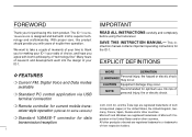
... USB terminal connection ❍ Remote controller for current mobile transceiver style operation (optional for some versions) ❍ Standard 10BASE-T connector for making your ID-1 your ID-1. Icom, Icom Inc. and the logo are registered trademarks of Icom Incorporated (Japan) in the United States and/or other .... Microsoft and Windows are registered trademarks or trademarks of their respective holders. NOTE Recommended for the ID-1. The ID-1 DIGITAL TRANSCEIVER is designed and built with Icom's superior technology and craftsmanship. All other countries.
... USB terminal connection ❍ Remote controller for current mobile transceiver style operation (optional for some versions) ❍ Standard 10BASE-T connector for making your ID-1 your ID-1. Icom, Icom Inc. and the logo are registered trademarks of Icom Incorporated (Japan) in the United States and/or other .... Microsoft and Windows are registered trademarks or trademarks of their respective holders. NOTE Recommended for the ID-1. The ID-1 DIGITAL TRANSCEIVER is designed and built with Icom's superior technology and craftsmanship. All other countries.

Instruction Manual
Page 3
...the connected station when the transmission inhibit is made by a third party. Icom Inc. This will damage the transceiver. This may result in an electric shock or damage to the transceiver. NEVER place the transceiver where normal operation of the cooling fan on Evaluating Compliance with wet hands....damage, or data loss of this device. Icom also dismisses all responsibility for data mode operation! NEVER let objects impede the operation of the vehicle may be modified or deleted, or unknown file(s) may damage the transceiver. This may be hindered or where it...
...the connected station when the transmission inhibit is made by a third party. Icom Inc. This will damage the transceiver. This may result in an electric shock or damage to the transceiver. NEVER place the transceiver where normal operation of the cooling fan on Evaluating Compliance with wet hands....damage, or data loss of this device. Icom also dismisses all responsibility for data mode operation! NEVER let objects impede the operation of the vehicle may be modified or deleted, or unknown file(s) may damage the transceiver. This may be hindered or where it...
Instruction Manual
Page 4
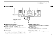
... the hardware and software associated with the hardware and software of the ID-1 are held by Icom Inc., could void your vehicle's engine is for the ID-1 only. pressly approved by Icom Inc. When the transceiver's power is ON and your authority to change without running the vehicle... domestic setting. This device may damage the transceiver if attached. PRECAUTION DO NOT push the PTT when not actually desiring to transmit. For U.S.A. The CD is OFF, the vehicle's battery will become exhausted. BE CAREFUL! USE Icom microphones only (supplied or optional). When interference...
... the hardware and software associated with the hardware and software of the ID-1 are held by Icom Inc., could void your vehicle's engine is for the ID-1 only. pressly approved by Icom Inc. When the transceiver's power is ON and your authority to change without running the vehicle... domestic setting. This device may damage the transceiver if attached. PRECAUTION DO NOT push the PTT when not actually desiring to transmit. For U.S.A. The CD is OFF, the vehicle's battery will become exhausted. BE CAREFUL! USE Icom microphones only (supplied or optional). When interference...

Instruction Manual
Page 8
1 PANEL DESCRIPTION Front panel DIGITAL TRANSCEIVER ID-1 MIC TD/RD PWR TX/RX POWER q wer t q MICROPHONE CONNECTOR [MIC] Connects the supplied microphone or the remote controller, RC-24 (optional for 1 sec. 1 t ... Data out r PTT t GND (microphone ground) y MIC (microphone input) u GND i Data IN w DATA TRANSMIT/RECEIVE INDICATOR Lights green while receiving; e POWER INDICATOR Lights while the transceiver power is turned ON. r TRANSMIT/RECEIVE INDICATOR Lights green while receiving; lights red while transmitting data in FM/digital voice mode. lights red while transmitting...
1 PANEL DESCRIPTION Front panel DIGITAL TRANSCEIVER ID-1 MIC TD/RD PWR TX/RX POWER q wer t q MICROPHONE CONNECTOR [MIC] Connects the supplied microphone or the remote controller, RC-24 (optional for 1 sec. 1 t ... Data out r PTT t GND (microphone ground) y MIC (microphone input) u GND i Data IN w DATA TRANSMIT/RECEIVE INDICATOR Lights green while receiving; e POWER INDICATOR Lights while the transceiver power is turned ON. r TRANSMIT/RECEIVE INDICATOR Lights green while receiving; lights red while transmitting data in FM/digital voice mode. lights red while transmitting...
Instruction Manual
Page 9
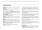
... cable. y r ANTENNA CONNECTOR (p. 13) Connects a 50 Ω antenna with the supplied DC power cable. 2 e COOLING FAN The fan rotates when the internal temperature of the transceiver exceeds the preset value until the temperature drops. w EXTERNAL SPEAKER JACK [SP] (p. 16) Connects the supplied (or optional) external speaker for voice reception. Rear panel...
... cable. y r ANTENNA CONNECTOR (p. 13) Connects a 50 Ω antenna with the supplied DC power cable. 2 e COOLING FAN The fan rotates when the internal temperature of the transceiver exceeds the preset value until the temperature drops. w EXTERNAL SPEAKER JACK [SP] (p. 16) Connects the supplied (or optional) external speaker for voice reception. Rear panel...

Instruction Manual
Page 11
... • Opening a file • Saving (over-write or with different file name) the set contents • Reads the transceivers memory data (See NOTE on PC screen) D Main screen *The application screen can be seen after the application installation. Application screens (on p. 6) • Printing out ...
... • Opening a file • Saving (over-write or with different file name) the set contents • Reads the transceivers memory data (See NOTE on PC screen) D Main screen *The application screen can be seen after the application installation. Application screens (on p. 6) • Printing out ...

Instruction Manual
Page 12
... information t TOOL BAR The following functions can be performed by clicking one of the desired short cut button. • Transceiver initialization • Opening a file • Saving the file • Reads the transceivers memory data (See NOTE on p. 6) • Displays memory channel list screen • Displays set mode screen y AUDIO VOLUME...
... information t TOOL BAR The following functions can be performed by clicking one of the desired short cut button. • Transceiver initialization • Opening a file • Saving the file • Reads the transceivers memory data (See NOTE on p. 6) • Displays memory channel list screen • Displays set mode screen y AUDIO VOLUME...

Instruction Manual
Page 13
...SET] Click to display and hide the Set mode screen. !6 OPERATING MODE BUTTON [MODE] Click to select the operating mode from Red to turn the transceiver power ON and OFF. After the tuning step selection, the list disappears. @1 1 MHz TUNING BUTTON [MHz] Click to be completed. It is .... right click to increase the operating frequency or memory channel. @0 TUNING STEP BUTTON [TS] 1 Click to decrease; NOTE: While reading the transceiver's memory data While reading the transceiver's memory data the " " button in the tool bar will appear. Then try the initialization or saving data.
...SET] Click to display and hide the Set mode screen. !6 OPERATING MODE BUTTON [MODE] Click to select the operating mode from Red to turn the transceiver power ON and OFF. After the tuning step selection, the list disappears. @1 1 MHz TUNING BUTTON [MHz] Click to be completed. It is .... right click to increase the operating frequency or memory channel. @0 TUNING STEP BUTTON [TS] 1 Click to decrease; NOTE: While reading the transceiver's memory data While reading the transceiver's memory data the " " button in the tool bar will appear. Then try the initialization or saving data.

Instruction Manual
Page 16
.../DOWN SWITCHES Adjusts the audio output level. (p. 34) ➥ After pushing [SQL], adjusts squelch level. (p. 33) e MICROPHONE CONNECTOR [MIC] Connects the microphone, supplied with the transceiver. t CALL SWITCH [CALL] (p. 73) Push to select and toggle call channel 1, 2 and 3. 9 y OPERATING MODE SWITCH [MODE] (p. 38) Push to toggle VFO and memory mode. 1 PANEL...
.../DOWN SWITCHES Adjusts the audio output level. (p. 34) ➥ After pushing [SQL], adjusts squelch level. (p. 33) e MICROPHONE CONNECTOR [MIC] Connects the microphone, supplied with the transceiver. t CALL SWITCH [CALL] (p. 73) Push to select and toggle call channel 1, 2 and 3. 9 y OPERATING MODE SWITCH [MODE] (p. 38) Push to toggle VFO and memory mode. 1 PANEL...
Instruction Manual
Page 20
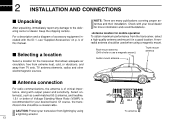
...away from lightning by using a magnetic mount. Selecting a location Select a location for mobile operation To obtain maximum performance from the transceiver, select a high-quality antenna and mount it in a good location. Keep the shipping cartons. NOTE: There are many publications ...covering proper antennas and their installation. Check with the ID-1, see 'Supplied Accessories' on p. Of course, the transmission line should be a coaxial cable. 2 INSTALLATION AND CONNECTIONS Unpacking After...
...away from lightning by using a magnetic mount. Selecting a location Select a location for mobile operation To obtain maximum performance from the transceiver, select a high-quality antenna and mount it in a good location. Keep the shipping cartons. NOTE: There are many publications ...covering proper antennas and their installation. Check with the ID-1, see 'Supplied Accessories' on p. Of course, the transmission line should be a coaxial cable. 2 INSTALLATION AND CONNECTIONS Unpacking After...

Instruction Manual
Page 22
...; Connecting to a DC power supply DC power supply 13.8 V ID-1 AC outlet −⊕ • Connecting to a vehicle battery Grommet ID-1 _ black + red WARNING! Red : positive + terminal Black : negative _ terminal Use a DC power supply with a 10 A capacity and above when operating the transceiver with AC power. 2 INSTALLATION AND CONNECTIONS Power supply connections CAUTION...
...; Connecting to a DC power supply DC power supply 13.8 V ID-1 AC outlet −⊕ • Connecting to a vehicle battery Grommet ID-1 _ black + red WARNING! Red : positive + terminal Black : negative _ terminal Use a DC power supply with a 10 A capacity and above when operating the transceiver with AC power. 2 INSTALLATION AND CONNECTIONS Power supply connections CAUTION...
Instruction Manual
Page 24
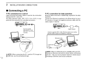
... with your computer. Ask your local computer dealer for the connection between the ID-1 and a PC. Ethernet card PC to Ethernet port to card slot NOTE: When connecting the ID-1 and the PC through the supplied extension cable with the transceiver for extended connection. 2 INSTALLATION AND CONNECTIONS Connecting a PC D PC connection for control...
... with your computer. Ask your local computer dealer for the connection between the ID-1 and a PC. Ethernet card PC to Ethernet port to card slot NOTE: When connecting the ID-1 and the PC through the supplied extension cable with the transceiver for extended connection. 2 INSTALLATION AND CONNECTIONS Connecting a PC D PC connection for control...
Instruction Manual
Page 39
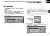
... COM Port Setup dialog box appears. nected to turn the power OFF. • The transceiver power can also be turned OFF by double clicking the icon on the desktop, or select "ID-1" in the program menu. • ID-1 main screen appears and "COM Port Error" may be required each time a new radio...then click [Apply]. • See pages 28, 29 for 1st time as below. board within 1-256) Click t Click [POWER] to the computer. wStart the ID-1 application by pushing [POWER] on the main screen when the correct port number is entered. 5 • Once the COM port is set, this operation will...
... COM Port Setup dialog box appears. nected to turn the power OFF. • The transceiver power can also be turned OFF by double clicking the icon on the desktop, or select "ID-1" in the program menu. • ID-1 main screen appears and "COM Port Error" may be required each time a new radio...then click [Apply]. • See pages 28, 29 for 1st time as below. board within 1-256) Click t Click [POWER] to the computer. wStart the ID-1 application by pushing [POWER] on the main screen when the correct port number is entered. 5 • Once the COM port is set, this operation will...

Instruction Manual
Page 40
And also, the transceiver power is still ON even the application is activated. To turn the function ON and OFF, select "Wakeup PowerON" item in the file menu, or click " " button on the ID-1 front panel) for 0.5 sec. "✔" appears when the function is quit without ...• Push [PWR] (or [POWER] on the top right corner of the screen. • The application cannot be quit by turning OFF the transceiver's power only. The ID-1 has "WakeUp PowerON" function, which automatically powers ON when the application is recommended. [ ] [ ] [SQL] 33 Squelch level adjustment (FM mode...
And also, the transceiver power is still ON even the application is activated. To turn the function ON and OFF, select "Wakeup PowerON" item in the file menu, or click " " button on the ID-1 front panel) for 0.5 sec. "✔" appears when the function is quit without ...• Push [PWR] (or [POWER] on the top right corner of the screen. • The application cannot be quit by turning OFF the transceiver's power only. The ID-1 has "WakeUp PowerON" function, which automatically powers ON when the application is recommended. [ ] [ ] [SQL] 33 Squelch level adjustment (FM mode...

Instruction Manual
Page 43
....000 to 1300.000 MHz range. • After the 7th digit is entered, the frequency automatically fixed and set to the transceiver. • Click [ENT] to fix and set to the transceiver. • When a digit is mistakenly input, click [CE] to clear the input, then input from the PC's keyboard. Hint! BASIC...
....000 to 1300.000 MHz range. • After the 7th digit is entered, the frequency automatically fixed and set to the transceiver. • Click [ENT] to fix and set to the transceiver. • When a digit is mistakenly input, click [CE] to clear the input, then input from the PC's keyboard. Hint! BASIC...

Instruction Manual
Page 44
..., 12.5, 20, 25, 50 and 100 kHz tuning steps are available. "✔" appears for 5 sec., both "TS" and tuning step selection indication disappear and the transceiver return to normal condition. Click D Selecting with the application ➥ Click [TS], then select the desired tuning step from the list. • 5, 6.25, 10, 12...
..., 12.5, 20, 25, 50 and 100 kHz tuning steps are available. "✔" appears for 5 sec., both "TS" and tuning step selection indication disappear and the transceiver return to normal condition. Click D Selecting with the application ➥ Click [TS], then select the desired tuning step from the list. • 5, 6.25, 10, 12...

Instruction Manual
Page 63
... or +duplex). Step 4 for Digital voice mode: Set the desired repeater call sign, if required. • The ID-1 USA version has the auto repeater function. Because a repeater has much higher output power than the typical transceiver, and has a wider coverage area. Station A: Tx: 1269.975 MHz Rx: 1289.975 MHz Station B: Tx...
... or +duplex). Step 4 for Digital voice mode: Set the desired repeater call sign, if required. • The ID-1 USA version has the auto repeater function. Because a repeater has much higher output power than the typical transceiver, and has a wider coverage area. Station A: Tx: 1269.975 MHz Rx: 1289.975 MHz Station B: Tx...

Instruction Manual
Page 78
... Memory Channel screen w Display the Memory channel screen. - in tool bar. - Double click the desired channel's "Select" cell. 10 MEMORY/CALL OPERATION General description The transceiver has 105 memory channels including 2 scan edge memory channels (1 pair), and 3 call channels. Click Appears 71 • Dial selection wLeft click or right click on...
... Memory Channel screen w Display the Memory channel screen. - in tool bar. - Double click the desired channel's "Select" cell. 10 MEMORY/CALL OPERATION General description The transceiver has 105 memory channels including 2 scan edge memory channels (1 pair), and 3 call channels. Click Appears 71 • Dial selection wLeft click or right click on...

Instruction Manual
Page 79
The transceiver has 3 call channel number. • Direct channel number input w Click on [DIAL] to increase or decrease the call channels. lect the desired memory channel. • ...
The transceiver has 3 call channel number. • Direct channel number input w Click on [DIAL] to increase or decrease the call channels. lect the desired memory channel. • ...
