
User Manual
Page 2
... certain switch is in a wellventilated area and work in good condition. Remove adjusting keys and wrenches. Direction of exposure varies, depending on . Make sure blade tension, tracking and blade guides are recommended. Do not remove jammed cutoff pieces until proper training and knowledge have impact resistant lenses; Cluttered areas and benches invite accidents. 9. If in OFF position before turning it frees both hands to use . 6. Before operating band saw...
... certain switch is in a wellventilated area and work in good condition. Remove adjusting keys and wrenches. Direction of exposure varies, depending on . Make sure blade tension, tracking and blade guides are recommended. Do not remove jammed cutoff pieces until proper training and knowledge have impact resistant lenses; Cluttered areas and benches invite accidents. 9. If in OFF position before turning it frees both hands to use . 6. Before operating band saw...
User Manual
Page 3
... its operation. Use a brush or compressed air to a complete stop. 40. Do not stand on a conversation and "horseplay" are careless acts that is turned "OFF", and keep safety key out of reach of parts, mounting and any machine operation. 34. Remove loose items and unnecessary work pieces from work area. Before further use . Keep floor around , carrying on machine. improper accessories may affect its intended function. Keep hands...
... its operation. Use a brush or compressed air to a complete stop. 40. Do not stand on a conversation and "horseplay" are careless acts that is turned "OFF", and keep safety key out of reach of parts, mounting and any machine operation. 34. Remove loose items and unnecessary work pieces from work area. Before further use . Keep floor around , carrying on machine. improper accessories may affect its intended function. Keep hands...
User Manual
Page 4
... 7.15 Guide post parallelism ...20 7.16 Changing blade speed ...20 7.17 Drive belt replacement and tensioning 21 7.18 Pulley alignment ...21 7.19 Brushes ...21 8.0 Operating controls ...21 8.1 Start/stop ...15 7.5 Leveling table insert ...16 7.6 Installing/changing blades ...16 7.7 Blade tension...17 7.8 Adjusting blade tension lever ...17 7.9 Blade tracking...17 7.10 Overview - 2.0 Table of contents Section Page 1.0 IMPORTANT SAFETY INSTRUCTIONS ...2 2.0 Table of contents...4 3.0 About this manual ...6 4.0 Specifications ...6 4.1 Specifications for JWBS-15...7 4.2 Specifications for JWBS...
... 7.15 Guide post parallelism ...20 7.16 Changing blade speed ...20 7.17 Drive belt replacement and tensioning 21 7.18 Pulley alignment ...21 7.19 Brushes ...21 8.0 Operating controls ...21 8.1 Start/stop ...15 7.5 Leveling table insert ...16 7.6 Installing/changing blades ...16 7.7 Blade tension...17 7.8 Adjusting blade tension lever ...17 7.9 Blade tracking...17 7.10 Overview - 2.0 Table of contents Section Page 1.0 IMPORTANT SAFETY INSTRUCTIONS ...2 2.0 Table of contents...4 3.0 About this manual ...6 4.0 Specifications ...6 4.1 Specifications for JWBS-15...7 4.2 Specifications for JWBS...

User Manual
Page 5
....0 User-maintenance ...25 10.1 Lubrication points ...25 10.2 Additional servicing ...25 11.0 Blade Selection Guide...26 12.0 Troubleshooting JWBS-series Band Saws 27 12.1 Operational problems ...27 12.2 Mechanical and electrical problems ...29 13.0 Replacement Parts...30 13.1.1 JWBS-15 Assembly - Parts List 39 13.5.1 JWBS-15 Upper Wheel Assembly - Exploded View 40 13.5.2 JWBS-15 Upper Wheel Assembly - Exploded View 43 13.9.2 JWBS-15/18/20 Miter Gauge Assembly - Exploded View 44 13.10.2 JWBS-18 Bandsaw Assembly - Parts List 50 13.13.1 JWBS-18 Upper Wheel Assembly...
....0 User-maintenance ...25 10.1 Lubrication points ...25 10.2 Additional servicing ...25 11.0 Blade Selection Guide...26 12.0 Troubleshooting JWBS-series Band Saws 27 12.1 Operational problems ...27 12.2 Mechanical and electrical problems ...29 13.0 Replacement Parts...30 13.1.1 JWBS-15 Assembly - Parts List 39 13.5.1 JWBS-15 Upper Wheel Assembly - Exploded View 40 13.5.2 JWBS-15 Upper Wheel Assembly - Exploded View 43 13.9.2 JWBS-15/18/20 Miter Gauge Assembly - Exploded View 44 13.10.2 JWBS-18 Bandsaw Assembly - Parts List 50 13.13.1 JWBS-18 Upper Wheel Assembly...
User Manual
Page 6
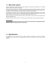
... serious injury! 4.0 Specifications The specifications in this manual before attempting assembly or operation! Failure to change specifications at our web site: www.jettools.com. If there are used in accordance with the instructions as set forth in this manual for a JET Model JWBS-15, JWBS-18 and JWBS-20 Band Saw. This manual contains instructions on installation, safety precautions, general operating procedures, maintenance instructions and parts breakdown. This manual is provided by JET, covering the safe operation and maintenance procedures for...
... serious injury! 4.0 Specifications The specifications in this manual before attempting assembly or operation! Failure to change specifications at our web site: www.jettools.com. If there are used in accordance with the instructions as set forth in this manual for a JET Model JWBS-15, JWBS-18 and JWBS-20 Band Saw. This manual contains instructions on installation, safety precautions, general operating procedures, maintenance instructions and parts breakdown. This manual is provided by JET, covering the safe operation and maintenance procedures for...
User Manual
Page 7
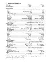
... . Miter gauge angle Left 45°, Right 45 Left 45°, Right 45° Dimensions: Footprint (base size), LxWxH 25-1/2 x 21-5/8 x 2 in. (648 x 549 x 51 mm Overall dimensions, LxWxH 29-1/2 x 32 x 74 in . (760 x 625 x 2020 mm)....... Shipping package dimensions 30 x 24-1/2 x 79-1/2 in . (750 x 812 x 1880 mm).......... 4.1 Specifications for JWBS-15 Model number JWBS-15 JWBS-15-3 Stock number 714600 714650 Band saw nominal size 15 in 15 in . Maximum blade width...
... . Miter gauge angle Left 45°, Right 45 Left 45°, Right 45° Dimensions: Footprint (base size), LxWxH 25-1/2 x 21-5/8 x 2 in. (648 x 549 x 51 mm Overall dimensions, LxWxH 29-1/2 x 32 x 74 in . (760 x 625 x 2020 mm)....... Shipping package dimensions 30 x 24-1/2 x 79-1/2 in . (750 x 812 x 1880 mm).......... 4.1 Specifications for JWBS-15 Model number JWBS-15 JWBS-15-3 Stock number 714600 714650 Band saw nominal size 15 in 15 in . Maximum blade width...

User Manual
Page 8
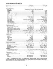
... the user to make a better estimation of blade with fence 16 in 16 in . 4.2 Specifications for JWBS-18 Model number JWBS-18 JWBS-18-3 Stock number 714700 714750 Band saw nominal size 18 in 18 in . Motor and electricals: Motor type totally-enclosed fan-cooled, induction, capacitor start Horsepower 1.75 HP 3 HP Phase single single Voltage 115/230V (prewired 115V 230V Cycle 60Hz 60Hz Listed FLA (full load amps 15/7.5 A 12 A Starting amps...
... the user to make a better estimation of blade with fence 16 in 16 in . 4.2 Specifications for JWBS-18 Model number JWBS-18 JWBS-18-3 Stock number 714700 714750 Band saw nominal size 18 in 18 in . Motor and electricals: Motor type totally-enclosed fan-cooled, induction, capacitor start Horsepower 1.75 HP 3 HP Phase single single Voltage 115/230V (prewired 115V 230V Cycle 60Hz 60Hz Listed FLA (full load amps 15/7.5 A 12 A Starting amps...
User Manual
Page 9
... Table, fence, miter gauge: Table dimensions 27-1/4 x 20 x 1-3/4 in 27-1/4 x 20 x 1-3/4 in . W x 0.35 in . W x 0.35 in . min. 157.1).......... 158 in . H 3/4 in . (max 158.9; As workplace conditions vary, this information is intended to allow the user to make a better estimation of blade with fence 4-1/2 in. (114 mm 4-1/2 in 1/8 to be seen as safe operating levels. Blade length 158 in . 4.3 Specifications for JWBS-20 Model number JWBS-20-3 JWBS...
... Table, fence, miter gauge: Table dimensions 27-1/4 x 20 x 1-3/4 in 27-1/4 x 20 x 1-3/4 in . W x 0.35 in . W x 0.35 in . min. 157.1).......... 158 in . H 3/4 in . (max 158.9; As workplace conditions vary, this information is intended to allow the user to make a better estimation of blade with fence 4-1/2 in. (114 mm 4-1/2 in 1/8 to be seen as safe operating levels. Blade length 158 in . 4.3 Specifications for JWBS-20 Model number JWBS-20-3 JWBS...
User Manual
Page 11
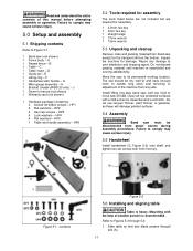
B 1 Table - G 1 Miter gauge assembly - HP3 4 Lock washers - HP6 5.2 Tools required for assembly The tools listed below are not included but are required for assembly. 1 2.5mm hex key 1 3mm hex key 1 straight edge 1 17mm wrench 1 13mm wrench 5.3 Unpacking and cleanup Remove crate and packing material from band saw blade passes through 5-4: 1. Report any side. Mounting with 3mm hex key. C 1 Table insert - E 1 Lifting ring - J 1 Owner's manual (not shown) 1 Warranty card (not shown) 1 Hardware package containing: 2 Socket hd button screws - Install lifting ring...
B 1 Table - G 1 Miter gauge assembly - HP3 4 Lock washers - HP6 5.2 Tools required for assembly The tools listed below are not included but are required for assembly. 1 2.5mm hex key 1 3mm hex key 1 straight edge 1 17mm wrench 1 13mm wrench 5.3 Unpacking and cleanup Remove crate and packing material from band saw blade passes through 5-4: 1. Report any side. Mounting with 3mm hex key. C 1 Table insert - E 1 Lifting ring - J 1 Owner's manual (not shown) 1 Warranty card (not shown) 1 Hardware package containing: 2 Socket hd button screws - Install lifting ring...
User Manual
Page 12
... following section. Install resaw fence (B) and tighten with lock washers and flat washers (Figure 5-4). Slide resaw fence against blade, making sure it .) 4. Tighten nuts on guide rail studs (A3) as shown, and tighten handle (A2) to lock position. Figure 5-4 Figure 5-7 Figure 5-5 12 2. Hand tighten screws only. 3. See Figure 5-5. (Do not deflect blade by inserting the two threaded studs into it contacts both front and back of miter slot, as needed . 6. Use a gauge to carefully...
... following section. Install resaw fence (B) and tighten with lock washers and flat washers (Figure 5-4). Slide resaw fence against blade, making sure it .) 4. Tighten nuts on guide rail studs (A3) as shown, and tighten handle (A2) to lock position. Figure 5-4 Figure 5-7 Figure 5-5 12 2. Hand tighten screws only. 3. See Figure 5-5. (Do not deflect blade by inserting the two threaded studs into it contacts both front and back of miter slot, as needed . 6. Use a gauge to carefully...
User Manual
Page 13
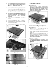
.... Tighten lock knob. 4. Repair or replace damaged or worn cord immediately. Tighten screw. The green colored rigid ear, lug, or the like the plug illustrated in sketch A in compliance with or without yellow stripes is the equipment-grounding conductor. Slide miter gauge into a matching outlet that looks like the adaptor illustrated in doubt as to whether the tool is properly grounded. Use a square to blade. 3. Figure 5-9 6.0 Electrical...
.... Tighten lock knob. 4. Repair or replace damaged or worn cord immediately. Tighten screw. The green colored rigid ear, lug, or the like the plug illustrated in sketch A in compliance with or without yellow stripes is the equipment-grounding conductor. Slide miter gauge into a matching outlet that looks like the adaptor illustrated in doubt as to whether the tool is properly grounded. Use a square to blade. 3. Figure 5-9 6.0 Electrical...

User Manual
Page 14
... 230 volts), make sure the cord rating is connected to Specifications for recommended circuit sizes. No adapter is installed. 1. and after the 230V plug is available or should be used with this tool. Make sure the tool is suitable for use on a different type of power and overheating. If the tool must be reconnected for use on the machine's motor plate. Model 714600, JWBS-15 714650, JWBS-15-3 714700, JWBS-18 714750, JWBS...
... 230 volts), make sure the cord rating is connected to Specifications for recommended circuit sizes. No adapter is installed. 1. and after the 230V plug is available or should be used with this tool. Make sure the tool is suitable for use on a different type of power and overheating. If the tool must be reconnected for use on the machine's motor plate. Model 714600, JWBS-15 714650, JWBS-15-3 714700, JWBS-18 714750, JWBS...
User Manual
Page 17
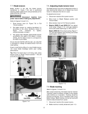
... tighten, counterclockwise to loosen. 3. Move tension lever to Blade Release position and remove blade. 3. Models JWBS-15 and JWBS-18: Turn adjust- Disconnect machine from power source before making any adjustments. Set blade tension by hand with machine disconnected from power source. 2. Move lever to Full Tension position. 4. Tip: When the band saw , you may find it necessary to change . this will prolong the blade's life. 7.8 Adjusting blade tension lever The blade tension lever has an adjustment screw or stop...
... tighten, counterclockwise to loosen. 3. Move tension lever to Blade Release position and remove blade. 3. Models JWBS-15 and JWBS-18: Turn adjust- Disconnect machine from power source before making any adjustments. Set blade tension by hand with machine disconnected from power source. 2. Move lever to Full Tension position. 4. Tip: When the band saw , you may find it necessary to change . this will prolong the blade's life. 7.8 Adjusting blade tension lever The blade tension lever has an adjustment screw or stop...
User Manual
Page 21
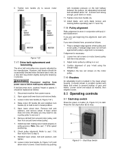
... tighten. 10. Loosen two set screws on button (A, Figure 8-1) to remove it. 6. If belt becomes worn, cracked, frayed or glazed, it seats properly in conjunction with moderate pressure on motor. 11. Remove bolt and washers, and remove wheel. Check pulley alignment. If you are properly adjusted by sliding in raised position. 8.0 Operating controls 8.1 Start/stop switch Press the green on the motor pulley. 7.19 Brushes Disconnect machine from power source before operating...
... tighten. 10. Loosen two set screws on button (A, Figure 8-1) to remove it. 6. If belt becomes worn, cracked, frayed or glazed, it seats properly in conjunction with moderate pressure on motor. 11. Remove bolt and washers, and remove wheel. Check pulley alignment. If you are properly adjusted by sliding in raised position. 8.0 Operating controls 8.1 Start/stop switch Press the green on the motor pulley. 7.19 Brushes Disconnect machine from power source before operating...

User Manual
Page 22
... on 1-3/4 HP models.) The switch has a safety feature that the guide bearings are properly adjusted for the machine to the guide rail. When cutting, do not overfeed the blade; See Figure 9-2. Using the fence in conjunction with the miter gauge. With band saw turned off, slide safety key (C, Figure 8-1) up when it to reach full speed. Adjust blade guide assembly so that prevents unauthorized or accidental starting of the way. 4. This piece must not...
... on 1-3/4 HP models.) The switch has a safety feature that the guide bearings are properly adjusted for the machine to the guide rail. When cutting, do not overfeed the blade; See Figure 9-2. Using the fence in conjunction with the miter gauge. With band saw turned off, slide safety key (C, Figure 8-1) up when it to reach full speed. Adjust blade guide assembly so that prevents unauthorized or accidental starting of the way. 4. This piece must not...
User Manual
Page 25
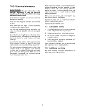
... appropriate capacity. Failure to adjust. If the power cord is worn, cut, or damaged in the upper and lower wheel housings. 10.0 User-maintenance Before any deposits from the band wheels to avoid vibration and blade breakage. Vacuum out the motor fan cover. 10.1 Lubrication points 1. Vacuum or blow out dust from inside cabinet. (Use proper dust mask equipment). Apply a light coat of guide post. 2.
... appropriate capacity. Failure to adjust. If the power cord is worn, cut, or damaged in the upper and lower wheel housings. 10.0 User-maintenance Before any deposits from the band wheels to avoid vibration and blade breakage. Vacuum out the motor fan cover. 10.1 Lubrication points 1. Vacuum or blow out dust from inside cabinet. (Use proper dust mask equipment). Apply a light coat of guide post. 2.
User Manual
Page 27
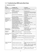
... wheels clean. Install correct blade. Correct accordingly. Contact service representative. Blade cutting inaccurately. Trunnion not lubricated. Drive belt too slack. Saw dust or debris on back edge of saw blade pitch. Workpiece being fed too quickly. Worn blade teeth or damaged blade. Correction * Tighten lock handle. Change to blade. Align fence properly. Fence not parallel to finer pitch blade. Blade tension too light. Disassemble and replace jammed parts. Position guides about 1/8" above workpiece. Adjust new constant contact with proper blade...
... wheels clean. Install correct blade. Correct accordingly. Contact service representative. Blade cutting inaccurately. Trunnion not lubricated. Drive belt too slack. Saw dust or debris on back edge of saw blade pitch. Workpiece being fed too quickly. Worn blade teeth or damaged blade. Correction * Tighten lock handle. Change to blade. Align fence properly. Fence not parallel to finer pitch blade. Blade tension too light. Disassemble and replace jammed parts. Position guides about 1/8" above workpiece. Adjust new constant contact with proper blade...
User Manual
Page 29
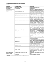
... is incorrect, you have a power supply problem. Clean motor of dust or debris to a voltmeter, you have a motor problem. Band Saw frequently trips. Replace with adequate size and length cord. Probable Cause No incoming power. If circuit size is correct, there is probably a loose electrical lead. Cord damaged. 12.2 Mechanical and electrical problems Table 5 Symptom Machine will not start /stop switch and establish if that band saw is on a circuit of...
... is incorrect, you have a power supply problem. Clean motor of dust or debris to a voltmeter, you have a motor problem. Band Saw frequently trips. Replace with adequate size and length cord. Probable Cause No incoming power. If circuit size is correct, there is probably a loose electrical lead. Cord damaged. 12.2 Mechanical and electrical problems Table 5 Symptom Machine will not start /stop switch and establish if that band saw is on a circuit of...

User Manual
Page 33
........... 13.1.2 JWBS-15 Assembly - Dust Collect Insert 1 33 Control Switch Assembly 3HP 1 JWBS15-143BSK...... Safety Key for JWBS15-143B (not shown 1 44 JWBS15-144 Motor Cord 14AWGx3C 1 45 TS-1533042 Pan Head Screw M5x12 2 46 JWBS15-146 Magnetic Switch Assembly 3HP only 1 JWBS15-146CS ........ Part No. Bushing ...1 22 JWBS15-122 Pin 3x20 1 23 JWBS15-123 Locate Block 1 24 BB-51201 Bearing 51201 1 25 PM1500-019 Upper Wheel Assembly 15 1 26...
........... 13.1.2 JWBS-15 Assembly - Dust Collect Insert 1 33 Control Switch Assembly 3HP 1 JWBS15-143BSK...... Safety Key for JWBS15-143B (not shown 1 44 JWBS15-144 Motor Cord 14AWGx3C 1 45 TS-1533042 Pan Head Screw M5x12 2 46 JWBS15-146 Magnetic Switch Assembly 3HP only 1 JWBS15-146CS ........ Part No. Bushing ...1 22 JWBS15-122 Pin 3x20 1 23 JWBS15-123 Locate Block 1 24 BB-51201 Bearing 51201 1 25 PM1500-019 Upper Wheel Assembly 15 1 26...

User Manual
Page 35
.... Table Insert...1 126 TS-1522011 Set Screw M5x5 3 127 JWBS15-1127........... Blade Guard Cover 1 111 PM1800B-093 Viewing Window 1 112 TS-1521011 Set Screw M4x4 2 113 5302731 Set Screw M8x6 4 114 TS-1550061 Flat Washer M8 4 115 TS-2361081 Spring Washer M8 4 116 TS-2248202 Socket Head Button Screw M8x20 4 117 TS-1523041 Set Screw M6x12 2 118 JWBS15-1118........... Guide Bar Bracket Assembly 1 121 JWBS15-1121........... Rip Fence Assembly 1 124 JWBS15-1124........... Roll Pin...
.... Table Insert...1 126 TS-1522011 Set Screw M5x5 3 127 JWBS15-1127........... Blade Guard Cover 1 111 PM1800B-093 Viewing Window 1 112 TS-1521011 Set Screw M4x4 2 113 5302731 Set Screw M8x6 4 114 TS-1550061 Flat Washer M8 4 115 TS-2361081 Spring Washer M8 4 116 TS-2248202 Socket Head Button Screw M8x20 4 117 TS-1523041 Set Screw M6x12 2 118 JWBS15-1118........... Guide Bar Bracket Assembly 1 121 JWBS15-1121........... Rip Fence Assembly 1 124 JWBS15-1124........... Roll Pin...


