Instruction Manual
Page 3
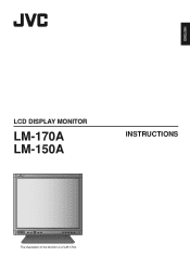
ENGLISH LCD DISPLAY MONITOR LM-170A LM-150A INSTRUCTIONS The illustration of the monitor is of LM-170A.
ENGLISH LCD DISPLAY MONITOR LM-170A LM-150A INSTRUCTIONS The illustration of the monitor is of LM-170A.
Instruction Manual
Page 4
... is connected. - NOTE: This equipment has been tested and found to radio communications. This equipment generates, uses and can be determined by turning the equipment off and on a circuit different from that to which can radiate radio frequency energy and, if not installed and used in accordance with the limits for a Class B digital device, pursuant to Part 15...
... is connected. - NOTE: This equipment has been tested and found to radio communications. This equipment generates, uses and can be determined by turning the equipment off and on a circuit different from that to which can radiate radio frequency energy and, if not installed and used in accordance with the limits for a Class B digital device, pursuant to Part 15...
Instruction Manual
Page 5
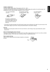
... not use only a correctly rated approved type, re-fit the fuse cover. (Consult your product dealer or local power company. Fuse 3 For U.S.A. If you are unable to insert the plug into ...replace the fuse. When replacing the fuse, be operated only with a grounding-type plug to the following power supply voltage and countries. The power cord attached conforms to satisfy FCC rule. ENGLISH POWER CONNECTION The power supply voltage rating of each countries. Use only the power cord designated to use the same power cord for AC 120 V as for United Kingdom power cord only The plug...
... not use only a correctly rated approved type, re-fit the fuse cover. (Consult your product dealer or local power company. Fuse 3 For U.S.A. If you are unable to insert the plug into ...replace the fuse. When replacing the fuse, be operated only with a grounding-type plug to the following power supply voltage and countries. The power cord attached conforms to satisfy FCC rule. ENGLISH POWER CONNECTION The power supply voltage rating of each countries. Use only the power cord designated to use the same power cord for AC 120 V as for United Kingdom power cord only The plug...
Instruction Manual
Page 6
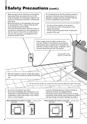
Safety Precautions (cont.) • Make enough room for a long time if the sound is controlled by items placed upon or against the product. • Do not hang on the product when installing the product on the wall. • Power-supply cords should be walked on or pinched by inserting or removing the power plug. • When the product is left unattended and...
Safety Precautions (cont.) • Make enough room for a long time if the sound is controlled by items placed upon or against the product. • Do not hang on the product when installing the product on the wall. • Power-supply cords should be walked on or pinched by inserting or removing the power plug. • When the product is left unattended and...
Instruction Manual
Page 7
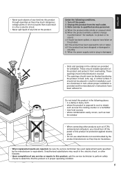
...connecting other hazards. • Upon completion of any service or repairs to this product, ask the service technician to perform safety checks to . f) When the power supply cord or plug is damaged. • Slots and openings in performance-for example, no picture or no sound. It should never be hazardous. • When replacement parts are provided for protection against electric shock. • Do not use...reliable operation of the product and protect it from the wall outlet. 3. Turn off the power of this product for ventilation. Unauthorized substitutions may result in...
...connecting other hazards. • Upon completion of any service or repairs to this product, ask the service technician to perform safety checks to . f) When the power supply cord or plug is damaged. • Slots and openings in performance-for example, no picture or no sound. It should never be hazardous. • When replacement parts are provided for protection against electric shock. • Do not use...reliable operation of the product and protect it from the wall outlet. 3. Turn off the power of this product for ventilation. Unauthorized substitutions may result in...
Instruction Manual
Page 9
ENGLISH Contents Safety Precautions 2 IMPORTANT SAFEGUARDS 2 Maintenance 6 Controls and Features 8 Front panel 8 Rear panel 10 Installation 11 Using the monitor on the stand 11 Installing the monitor on the wall 12 Installing the monitor on the rack 12 How to Use the MAIN MENU 13 MAIN MENU items 13 How to Use the SET-UP MENU 14 SET-UP MENU items 15 How to Use the External Control 17 About the external control 17 How to use the MAKE/TRIGGER terminal 17 Troubleshooting 18 Specifications 20 Dimensions 21 Available computer signals 22 7
ENGLISH Contents Safety Precautions 2 IMPORTANT SAFEGUARDS 2 Maintenance 6 Controls and Features 8 Front panel 8 Rear panel 10 Installation 11 Using the monitor on the stand 11 Installing the monitor on the wall 12 Installing the monitor on the rack 12 How to Use the MAIN MENU 13 MAIN MENU items 13 How to Use the SET-UP MENU 14 SET-UP MENU items 15 How to Use the External Control 17 About the external control 17 How to use the MAKE/TRIGGER terminal 17 Troubleshooting 18 Specifications 20 Dimensions 21 Available computer signals 22 7
Instruction Manual
Page 10
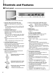
... button (2) while pressing the MENU button. (+ page 14) 7 SCAN SIZE button/lamp Selects the screen size. ADJ. (USER)" on the top and the bottom of the screen because the aspect ratio of the LCD panel is 5:4. • When "USER" is not displayed, adjust the volume level (00 to the next step. • Performs the selected function. 5 Volume control button (LM-170A only)*2 While the menu is selected, horizontal/vertical size and position can be manually adjusted. (+ "SIZE...
... button (2) while pressing the MENU button. (+ page 14) 7 SCAN SIZE button/lamp Selects the screen size. ADJ. (USER)" on the top and the bottom of the screen because the aspect ratio of the LCD panel is 5:4. • When "USER" is not displayed, adjust the volume level (00 to the next step. • Performs the selected function. 5 Volume control button (LM-170A only)*2 While the menu is selected, horizontal/vertical size and position can be manually adjusted. (+ "SIZE...
Instruction Manual
Page 11
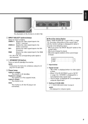
... input changes. VIDEO 2: Selects the video signal input to the DVI- DVI: Selects the video signal input to the VIDEO 2 terminal. p Power lamp Lights in the suspend mode. VIDEO 1 NTSC OVER 1 Input status 2 Signal format • "NO SYNC" is displayed when no video signal is input. • When "COLOR SYSTEM" is set to "ON" (+ page 16), the status (information of the current input and the monitor settings) is displayed for computer signals. 9 ENGLISH 8 9p The illustration of the monitor is of LM-170A. 8 INPUT...
... input changes. VIDEO 2: Selects the video signal input to the DVI- DVI: Selects the video signal input to the VIDEO 2 terminal. p Power lamp Lights in the suspend mode. VIDEO 1 NTSC OVER 1 Input status 2 Signal format • "NO SYNC" is displayed when no video signal is input. • When "COLOR SYSTEM" is set to "ON" (+ page 16), the status (information of the current input and the monitor settings) is displayed for computer signals. 9 ENGLISH 8 9p The illustration of the monitor is of LM-170A. 8 INPUT...
Instruction Manual
Page 12
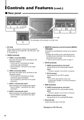
... analog RGB signals. 6 Security slot Install a security wire to this terminal or by inputting the pulse signal. + "How to be controlled by shortcircuiting the pin terminal in speaker of LM-170A. 1 1 AC inlet Power input connector. d AUDIO 2 terminal (pin jack)* Input terminal for the analog audio signals. • Use the VIDEO 2 terminal for the video connection. 3 REMOTE (external control) terminal (MAKE/ TRIGGER) Terminals for controlling the monitor by an external control. • Enables the monitor to Use the External Control...
... analog RGB signals. 6 Security slot Install a security wire to this terminal or by inputting the pulse signal. + "How to be controlled by shortcircuiting the pin terminal in speaker of LM-170A. 1 1 AC inlet Power input connector. d AUDIO 2 terminal (pin jack)* Input terminal for the analog audio signals. • Use the VIDEO 2 terminal for the video connection. 3 REMOTE (external control) terminal (MAKE/ TRIGGER) Terminals for controlling the monitor by an external control. • Enables the monitor to Use the External Control...
Instruction Manual
Page 13
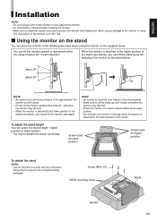
... the monitor or lean against the monitor. • Do not hold the LCD panel when installing the monitor. • Make sure to install the monitor securely to prevent the monitor from falling over . • Place the monitor on the supplied stand. ENGLISH Installation NOTE: • Do not rest your fingers in this way when the monitor is attached to the lower position of the stand. Screw (M4 x 10) VESA mounting holes Stand Monitor...
... the monitor or lean against the monitor. • Do not hold the LCD panel when installing the monitor. • Make sure to install the monitor securely to prevent the monitor from falling over . • Place the monitor on the supplied stand. ENGLISH Installation NOTE: • Do not rest your fingers in this way when the monitor is attached to the lower position of the stand. Screw (M4 x 10) VESA mounting holes Stand Monitor...
Instruction Manual
Page 14
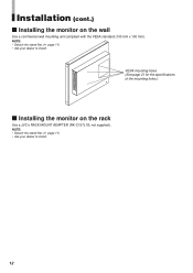
not supplied). NOTE: • Detach the stand first. (+ page 11) • Ask your dealer to install. 12 VESA mounting holes (See page 21 for the specifications of the mounting holes.) 7 Installing the monitor on the wall Use a commercial wall mounting unit compliant with the VESA standard (100 mm x 100 mm). Installation (cont.) 7 Installing the monitor on the rack Use a JVC's RACK MOUNT ADAPTER (RK-C157L1G; NOTE: • Detach the stand first. (+ page 11) • Ask your dealer to install.
not supplied). NOTE: • Detach the stand first. (+ page 11) • Ask your dealer to install. 12 VESA mounting holes (See page 21 for the specifications of the mounting holes.) 7 Installing the monitor on the wall Use a commercial wall mounting unit compliant with the VESA standard (100 mm x 100 mm). Installation (cont.) 7 Installing the monitor on the rack Use a JVC's RACK MOUNT ADAPTER (RK-C157L1G; NOTE: • Detach the stand first. (+ page 11) • Ask your dealer to install.
Instruction Manual
Page 15
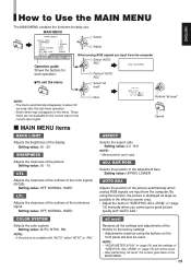
... screen goes back to the MAIN MENU. 13 Setting value: 00 - 25 SHARPNESS Adjusts the clearness of the luminance signal. COLOR SYSTEM Selects the color system. Setting value: OFF, NORMAL, HARD LTI. ADJ. (RGB)" (+ page 15) will also be reset. • After performing "all reset" Cancel BACK LIGHT Adjusts the brightness of the monitor to the factory settings. • Adjustments made by using this function, the picture is unstable with "AUTO ADJ." Adjusts...
... screen goes back to the MAIN MENU. 13 Setting value: 00 - 25 SHARPNESS Adjusts the clearness of the luminance signal. COLOR SYSTEM Selects the color system. Setting value: OFF, NORMAL, HARD LTI. ADJ. (RGB)" (+ page 15) will also be reset. • After performing "all reset" Cancel BACK LIGHT Adjusts the brightness of the monitor to the factory settings. • Adjustments made by using this function, the picture is unstable with "AUTO ADJ." Adjusts...
Instruction Manual
Page 16
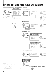
Select When video signals are input and "SCAN SIZE" is "4:3" When analog RGB signals are not available for each operation. 7 To exit the menu: Next Adjust Select "reset" 7 COLOR TEMP. When "ASPECT" is "USER" Next Select Adjust Ex. This item is not selectable. 14 7 NO SYNC FUNCTION Select Select Next Adjust 7 REMOTE SYSTEM 7 STATUS DISPLAY 7 CONTROL LOCK Select Adjust (+ page 16) 7 To go back to Use the SET-UP MENU The SET-UP MENU contains the...
Select When video signals are input and "SCAN SIZE" is "4:3" When analog RGB signals are not available for each operation. 7 To exit the menu: Next Adjust Select "reset" 7 COLOR TEMP. When "ASPECT" is "USER" Next Select Adjust Ex. This item is not selectable. 14 7 NO SYNC FUNCTION Select Select Next Adjust 7 REMOTE SYSTEM 7 STATUS DISPLAY 7 CONTROL LOCK Select Adjust (+ page 16) 7 To go back to Use the SET-UP MENU The SET-UP MENU contains the...
Instruction Manual
Page 17
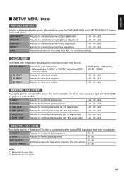
... - 00 - +40 -40 - 00 - +40 SIZE/POSI. H. ADJ. (RGB) Adjusts the position of each signal. 15 ENGLISH 7 SET-UP MENU items PICTURE SUB ADJ. SIZE*1 Adjusts the horizontal picture size. -40 - 00 - +40 H. POSI.*1 Adjusts the horizontal picture position. -40 - 00 - +40 V. This item is set to the factory settings. POSI.*2 Adjusts the vertical picture position. 00 - 99 DOT CLOCK*2 CLOCK PHASE*2 00 - 99 Eliminates stripes or flickering by using the CHROMA/PHASE and CONTRAST/BRIGHT buttons on the front...
... - 00 - +40 -40 - 00 - +40 SIZE/POSI. H. ADJ. (RGB) Adjusts the position of each signal. 15 ENGLISH 7 SET-UP MENU items PICTURE SUB ADJ. SIZE*1 Adjusts the horizontal picture size. -40 - 00 - +40 H. POSI.*1 Adjusts the horizontal picture position. -40 - 00 - +40 V. This item is set to the factory settings. POSI.*2 Adjusts the vertical picture position. 00 - 99 DOT CLOCK*2 CLOCK PHASE*2 00 - 99 Eliminates stripes or flickering by using the CHROMA/PHASE and CONTRAST/BRIGHT buttons on the front...
Instruction Manual
Page 18
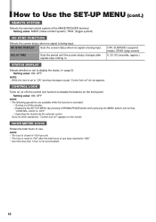
... SYNC DISPLAY Sets the screen status when no signal is shown in . DELAY TIME Sets the period until the screen status changes after the total hours of use . NOTE: • The hour is being input. Setting value: MAKE (make contact system), TRIG. (trigger system) NO SYNC FUNCTION Selects the screen status when no signal is reset to "ON," warning messages except "Control lock on !" OFF, SUSPEND (suspend mode), GRAY (gray screen...
... SYNC DISPLAY Sets the screen status when no signal is shown in . DELAY TIME Sets the period until the screen status changes after the total hours of use . NOTE: • The hour is being input. Setting value: MAKE (make contact system), TRIG. (trigger system) NO SYNC FUNCTION Selects the screen status when no signal is reset to "ON," warning messages except "Control lock on !" OFF, SUSPEND (suspend mode), GRAY (gray screen...
Instruction Manual
Page 19
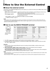
... about 1 second. from "REMOTE SYSTEM" in the SET-UP MENU. + "REMOTE SYSTEM" on page 16 NOTE: • When using the make contact system, you cannot use the buttons on the front panel or menu to utilize functions which allows you to control the monitor by the MAKE (make contact) system, only one terminal must be short-circuited. (Other terminals must be opened.) • When selecting...
... about 1 second. from "REMOTE SYSTEM" in the SET-UP MENU. + "REMOTE SYSTEM" on page 16 NOTE: • When using the make contact system, you cannot use the buttons on the front panel or menu to utilize functions which allows you to control the monitor by the MAKE (make contact) system, only one terminal must be short-circuited. (Other terminals must be opened.) • When selecting...
Instruction Manual
Page 20
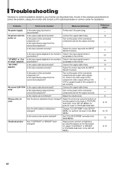
... (video output setting of the VCR or graphic board of the computer) is set to the monitor's Check if the input signal format is of the connected component and set the output correctly. Adjust the picture by using the buttons on ? Or, adjust "CONTRAST" or "BRIGHT" in the MAIN MENU. No picture with the power on the power of range" appears. Connect the signal cable firmly. Turn on Is the signal cable disconnected? Or, perform "all reset" in "PICTURE SUB...
... (video output setting of the VCR or graphic board of the computer) is set to the monitor's Check if the input signal format is of the connected component and set the output correctly. Adjust the picture by using the buttons on ? Or, adjust "CONTRAST" or "BRIGHT" in the MAIN MENU. No picture with the power on the power of range" appears. Connect the signal cable firmly. Turn on Is the signal cable disconnected? Or, perform "all reset" in "PICTURE SUB...

Instruction Manual
Page 21
.... • The red spots, blue spots and green spots on the menu. Some items do not function. Installing the driver is required when a computer is built with the graphic board). - ENGLISH Problems Points to be displayed fully in the effective screen area. Is the input signal adapted to "4:3." Is "CONTROL LOCK" in the SET-UP MENU set the monitor to "ON"? Disable the external control. Or, set to the standard display. • Recommended display setting: 1280...
.... • The red spots, blue spots and green spots on the menu. Some items do not function. Installing the driver is required when a computer is built with the graphic board). - ENGLISH Problems Points to be displayed fully in the effective screen area. Is the input signal adapted to "4:3." Is "CONTROL LOCK" in the SET-UP MENU set the monitor to "ON"? Disable the external control. Or, set to the standard display. • Recommended display setting: 1280...
Instruction Manual
Page 22
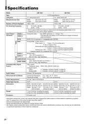
... the stand) (without the stand) Width: 342 mm (13 1/2") 342 mm (13 1/2") Height: 330.6 mm (13 1/8") 291 mm (11 1/2") Depth: 184 mm (7 1/4") 70.5 mm (2 7/8") (with DDC2B. Specifications Model LM-170A LM-150A Type LCD Display Monitor LCD panel 17", active matrix TFT 15", active matrix TFT Effective Screen Size Width: Height: 337.9 mm (13 1/4") 270.3 mm (10 5/8") Width: Height: 304.1 mm (11 15/16") 228.1 mm (8 15/16") Number of Pixels Displayed...
... the stand) (without the stand) Width: 342 mm (13 1/2") 342 mm (13 1/2") Height: 330.6 mm (13 1/8") 291 mm (11 1/2") Depth: 184 mm (7 1/4") 70.5 mm (2 7/8") (with DDC2B. Specifications Model LM-170A LM-150A Type LCD Display Monitor LCD panel 17", active matrix TFT 15", active matrix TFT Effective Screen Size Width: Height: 337.9 mm (13 1/4") 270.3 mm (10 5/8") Width: Height: 304.1 mm (11 15/16") 228.1 mm (8 15/16") Number of Pixels Displayed...
Instruction Manual
Page 24
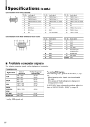
... computer signals can be displayed on the monitor. does not solve the problem, adjust the items in this table • If the picture of the RGB terminal (D-sub 15-pin) Pin No. Specifications (cont.) Specification of the DVI-D terminal 9 1 8 16 Pin No. Input signal 9 T.M.D.S Data 1- 10 T.M.D.S Data 1+ 11 T.M.D.S Data 1/3 shield 12 NC 13 NC 14 +5 V Power 15 GND 16 Hot Plug Detect Pin No. Input signal 1 Red 2 Green 3 Blue...
... computer signals can be displayed on the monitor. does not solve the problem, adjust the items in this table • If the picture of the RGB terminal (D-sub 15-pin) Pin No. Specifications (cont.) Specification of the DVI-D terminal 9 1 8 16 Pin No. Input signal 9 T.M.D.S Data 1- 10 T.M.D.S Data 1+ 11 T.M.D.S Data 1/3 shield 12 NC 13 NC 14 +5 V Power 15 GND 16 Hot Plug Detect Pin No. Input signal 1 Red 2 Green 3 Blue...

