
Installation Instructions
Page 1
... and Outdoor Units 5-5. COOL / DRY Model This air conditioner uses the new refrigerant R410A. Install the Rear Panel on a Wall 8. Flaring Procedure with Unit 1-3. Tools Required for the Outdoor Unit 3. Outdoor Unit 2-3. Wiring Instructions 3-7. Wiring Instructions for Installation 2. 05-424 KS0971-1271 12/13/05 1:27 PM Page a INSTALLATION INSTRUCTIONS - Mounting on the Wall 3-4. Additional Materials...
... and Outdoor Units 5-5. COOL / DRY Model This air conditioner uses the new refrigerant R410A. Install the Rear Panel on a Wall 8. Flaring Procedure with Unit 1-3. Tools Required for the Outdoor Unit 3. Outdoor Unit 2-3. Wiring Instructions 3-7. Wiring Instructions for Installation 2. 05-424 KS0971-1271 12/13/05 1:27 PM Page a INSTALLATION INSTRUCTIONS - Mounting on the Wall 3-4. Additional Materials...

Installation Instructions
Page 2
...supply power to provide a solid, level foundation for Heat Pump-type Systems) Install the outdoor unit on the air conditioner can cause dripping and water damage to walls and floors. ...In Moist or Uneven Locations Use a raised concrete pad or concrete blocks to the unit until ...warning and caution notices given in this manual. When Installing... ...In a Ceiling or Wall Make sure the ceiling/wall is higher than drifting snow. Provide snow vents. Please Read Before Starting This air conditioning system meets strict safety and operating standards. q Observe all you finish, remembering...
...supply power to provide a solid, level foundation for Heat Pump-type Systems) Install the outdoor unit on the air conditioner can cause dripping and water damage to walls and floors. ...In Moist or Uneven Locations Use a raised concrete pad or concrete blocks to the unit until ...warning and caution notices given in this manual. When Installing... ...In a Ceiling or Wall Make sure the ceiling/wall is higher than drifting snow. Provide snow vents. Please Read Before Starting This air conditioning system meets strict safety and operating standards. q Observe all you finish, remembering...
Installation Instructions
Page 4
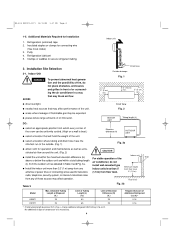
...air conditioner in Table 3 and Fig. 3a. 05-424 KS0971-1271 12/13/05 1:27 PM Page 4 1-5. Refrigeration (armored) tape 2. Indoor Unit WARNING AVOID: To prevent abnormal heat generation and the possibility of fire, do not (L) from which every corner of the room can be uniformly cooled. (High on a wall... is necessary. 4 Fig. 2 q areas where leakage of the unit. install wall-mounted type Minimum height q Install the indoor unit more than 3.3' (1 m) away from any of the Wall above or below the outdoor unit and within...
...air conditioner in Table 3 and Fig. 3a. 05-424 KS0971-1271 12/13/05 1:27 PM Page 4 1-5. Refrigeration (armored) tape 2. Indoor Unit WARNING AVOID: To prevent abnormal heat generation and the possibility of fire, do not (L) from which every corner of the room can be uniformly cooled. (High on a wall... is necessary. 4 Fig. 2 q areas where leakage of the unit. install wall-mounted type Minimum height q Install the indoor unit more than 3.3' (1 m) away from any of the Wall above or below the outdoor unit and within...
Installation Instructions
Page 5
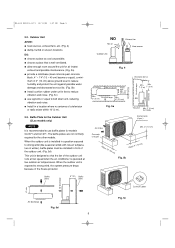
...Exhaust fan Heat source Fig. 4 Air intake Min. 2" (5 cm) Valve side Min. 10" (25 cm) Min. 05-424 KS0971-1271 12/13/05 1:27 PM Page 5 2-2. Outdoor Unit AVOID: q heat sources, exhaust fans, etc. (Fig. 4) q damp, humid or uneven locations. DO: q choose a place as cool as possible. When the outdoor unit..., the system pressure drops because of the outdoor unit. (Fig. 5d) This unit is designed so that is operated at low speed when the air conditioner is well ventilated. The baffle plates are not normally required for models CL0971 and CL1271. q allow enough room around the unit for...
...Exhaust fan Heat source Fig. 4 Air intake Min. 2" (5 cm) Valve side Min. 10" (25 cm) Min. 05-424 KS0971-1271 12/13/05 1:27 PM Page 5 2-2. Outdoor Unit AVOID: q heat sources, exhaust fans, etc. (Fig. 4) q damp, humid or uneven locations. DO: q choose a place as cool as possible. When the outdoor unit..., the system pressure drops because of the outdoor unit. (Fig. 5d) This unit is designed so that is operated at low speed when the air conditioner is well ventilated. The baffle plates are not normally required for models CL0971 and CL1271. q allow enough room around the unit for...
Installation Instructions
Page 10
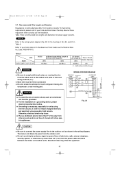
AWG (American Wire Gauge) Power supply Single phase 115V 60HZ WARNING q Be sure to the wiring system diagram (Fig. 23) for power supply systems. NOTE Refer to comply with other grounds and ... codes. q Do not run wiring for units using inverter circuits, in order to the outdoor unit as shown in the absence of electric shock, each air conditioner unit must be allowed to the outdoor unit (size of wire and wiring method, etc.). q Each wire must be grounded. q For the installation of (A), (B), and...
AWG (American Wire Gauge) Power supply Single phase 115V 60HZ WARNING q Be sure to the wiring system diagram (Fig. 23) for power supply systems. NOTE Refer to comply with other grounds and ... codes. q Do not run wiring for units using inverter circuits, in order to the outdoor unit as shown in the absence of electric shock, each air conditioner unit must be allowed to the outdoor unit (size of wire and wiring method, etc.). q Each wire must be grounded. q For the installation of (A), (B), and...
Installation Instructions
Page 17
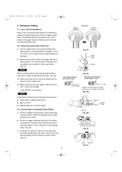
... Connecting Tubes Tightly a) Be sure to apply a sealing cap or water-proof tape to prevent dust or water from the unit and be sure to mount it on the copper tube. (4) Make a flare at the end of copper tube with a flare tool.* (Figs. 49a and 49b) (*Use "RIGID" or ...tubes which run between indoor and outdoor units. Refrigerant Tubing 5-1. It is as shown in the flare nut lightly at the end of the conventional split system air conditioners employ the flaring method to obtain a smooth match. (Fig. 51) Before Deburring After Fig. 47 Copper tubing Reamer If the special R410A flare...
... Connecting Tubes Tightly a) Be sure to apply a sealing cap or water-proof tape to prevent dust or water from the unit and be sure to mount it on the copper tube. (4) Make a flare at the end of copper tube with a flare tool.* (Figs. 49a and 49b) (*Use "RIGID" or ...tubes which run between indoor and outdoor units. Refrigerant Tubing 5-1. It is as shown in the flare nut lightly at the end of the conventional split system air conditioners employ the flaring method to obtain a smooth match. (Fig. 51) Before Deburring After Fig. 47 Copper tubing Reamer If the special R410A flare...
Installation Instructions
Page 20
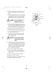
... next page.) (13) While the air conditioner is running , close it to 170 lbs·in (200 kgf·cm) with a torque wrench. CAUTION This may cause the refrigerant gas to avoid this, take off the hose quickly. (11) Fasten the valve cap on the narrow tube service valve counter-clockwise by...Bubbles indicate a leak. Tighten the joint more when leaks, then check if there is no leak. In order to leak. Next, mount the valve cap on the tubing. This completes air purging with a clean cloth. (8) With the hex wrench, turn ) Narrow tube Hex wrench Wide tube Valve cap Vacuum hose to ...
... next page.) (13) While the air conditioner is running , close it to 170 lbs·in (200 kgf·cm) with a torque wrench. CAUTION This may cause the refrigerant gas to avoid this, take off the hose quickly. (11) Fasten the valve cap on the narrow tube service valve counter-clockwise by...Bubbles indicate a leak. Tighten the joint more when leaks, then check if there is no leak. In order to leak. Next, mount the valve cap on the tubing. This completes air purging with a clean cloth. (8) With the hex wrench, turn ) Narrow tube Hex wrench Wide tube Valve cap Vacuum hose to ...
Installation Instructions
Page 21
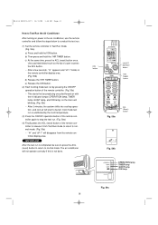
The air conditioner will not operate correctly if this is completed, be felt. e) Release the ION button. (2) Start Cooling mode test run by the room temperature. (3) Press the ON/OFF operation button of the remote controller again to stop the test run. (Fig. 59a) (4) ... 05-424 KS0971-1271 12/13/05 1:28 PM Page 21 How to Test Run the Air Conditioner After turning on the main unit blinking. (Fig. 59c) • After 3 minutes, the system shifts into cooling operation, and cool air will start to be sure to press the ACL (reset) button to return to normal mode...
The air conditioner will not operate correctly if this is completed, be felt. e) Release the ION button. (2) Start Cooling mode test run by the room temperature. (3) Press the ON/OFF operation button of the remote controller again to stop the test run. (Fig. 59a) (4) ... 05-424 KS0971-1271 12/13/05 1:28 PM Page 21 How to Test Run the Air Conditioner After turning on the main unit blinking. (Fig. 59c) • After 3 minutes, the system shifts into cooling operation, and cool air will start to be sure to press the ACL (reset) button to return to normal mode...
Installation Instructions
Page 22
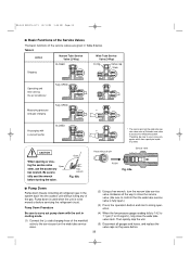
...Way) CLOSED Wide Tube Service Valve (3-Way) O-ring Valve cap Stem Operating and test running the air conditioner Fully OPEN Fully OPEN Measuring pressure * and gas charging Air purging with the unit in cooling mode. (1) Connect the Lo side charging hose of the gas. Therefore, be moved or before ...) Service valve PUSH Fig. 60a s Pump Down Pump down is used when the unit is fully open.) (3) Press the operation button and start cooling operation. (4) When the low pressure gauge reading falls to 14.2 to 7.1 psi (1 to access the refrigerant system. Be sure to use the accessory...
...Way) CLOSED Wide Tube Service Valve (3-Way) O-ring Valve cap Stem Operating and test running the air conditioner Fully OPEN Fully OPEN Measuring pressure * and gas charging Air purging with the unit in cooling mode. (1) Connect the Lo side charging hose of the gas. Therefore, be moved or before ...) Service valve PUSH Fig. 60a s Pump Down Pump down is used when the unit is fully open.) (3) Press the operation button and start cooling operation. (4) When the low pressure gauge reading falls to 14.2 to 7.1 psi (1 to access the refrigerant system. Be sure to use the accessory...
Installation Instructions
Page 23
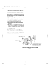
...can connect the remote control unit to indicate that location. trol unit and the air conditioner (since a check signal is covered q More than 26' (8 m) away from either a non-fixed position or a wall-mounted position. To take out the remote control unit, pull it has received the signal.... To ensure that the air conditioner operates correctly, do not install the remote control unit in place Hole To prevent loss of the air conditioner's airstream q Where it may become...
...can connect the remote control unit to indicate that location. trol unit and the air conditioner (since a check signal is covered q More than 26' (8 m) away from either a non-fixed position or a wall-mounted position. To take out the remote control unit, pull it has received the signal.... To ensure that the air conditioner operates correctly, do not install the remote control unit in place Hole To prevent loss of the air conditioner's airstream q Where it may become...
Installation Instructions
Page 24
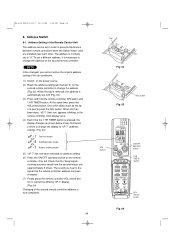
... in the remote controller clock display area. (4) Each time the 1 HR TIMER button is pressed, the display changes as the tip of the air conditioner. (1) Switch on the power source. (2) Break the address-setting tab marked "A" on the second remote controller to change the address on the ...address has been changed , you hear is the signal that the "beep"signalreceived sound is necessary to prevent interference between remote controllers when two Sanyo indoor units are installed near each other. Use a thin object such as shown below. Address Switch 8-1. NOTE Once changed . (7) Finally ...
... in the remote controller clock display area. (4) Each time the 1 HR TIMER button is pressed, the display changes as the tip of the air conditioner. (1) Switch on the power source. (2) Break the address-setting tab marked "A" on the second remote controller to change the address on the ...address has been changed , you hear is the signal that the "beep"signalreceived sound is necessary to prevent interference between remote controllers when two Sanyo indoor units are installed near each other. Use a thin object such as shown below. Address Switch 8-1. NOTE Once changed . (7) Finally ...


