Operater's Manual
Page 1
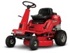
Description 7800784 2811524BV 7800785 2812524BVE 7800786 3014524BVE 7800787 3317524BVE RNeoptrfoodruction ! Manual No. 7104742 (Rev. '-') Operator's Manual REAR ENGINE RIDING MOWER SERIES 24 Model No.
Description 7800784 2811524BV 7800785 2812524BVE 7800786 3014524BVE 7800787 3317524BVE RNeoptrfoodruction ! Manual No. 7104742 (Rev. '-') Operator's Manual REAR ENGINE RIDING MOWER SERIES 24 Model No.
Operater's Manual
Page 3
Wash hands after handling. ! WARNING ! WARNING ! Engine exhaust, some of its constituents, and certain vehicle components contain or emit chemicals known to the State of California to cause cancer and birth ... Cutting Height Adjustment 15 Reverse Lockout Mechanism 16 Maintenance 17 Maintenance Chart 17 r n General Maintenance 18 Storage 23 fo tio Engine Adjustments and Repairs 24 Mower Deck and Component Adjustments 24 Rear Engine Rider Drive Components 27 t c Mower Blade Replacement 28 o Mower Drive Belt Replacement 29 u Battery 30 N d Troubleshooting 32 ro Warranty ...
Wash hands after handling. ! WARNING ! WARNING ! Engine exhaust, some of its constituents, and certain vehicle components contain or emit chemicals known to the State of California to cause cancer and birth ... Cutting Height Adjustment 15 Reverse Lockout Mechanism 16 Maintenance 17 Maintenance Chart 17 r n General Maintenance 18 Storage 23 fo tio Engine Adjustments and Repairs 24 Mower Deck and Component Adjustments 24 Rear Engine Rider Drive Components 27 t c Mower Blade Replacement 28 o Mower Drive Belt Replacement 29 u Battery 30 N d Troubleshooting 32 ro Warranty ...
Operater's Manual
Page 10
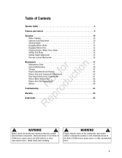
...securely. With the blade o pedals depressed, the shift lever must not go into r reverse. 7. Add fuel to the fuel tank after pushing the Rear Engine R Rider outside where fumes can be necessary to make sure all e times. 8. IMPORTANT: Do not overfill. (See statement below.) IMPORTANT To ... the Reverse Lockout Mechanism. Operation Before Starting Make the following checks and perform the service required before standing the machine on its rear bumper. 10 www.snapper.com If the u blade pedals are in the filler neck. • Empty the fuel tank before each start-up to ...
...securely. With the blade o pedals depressed, the shift lever must not go into r reverse. 7. Add fuel to the fuel tank after pushing the Rear Engine R Rider outside where fumes can be necessary to make sure all e times. 8. IMPORTANT: Do not overfill. (See statement below.) IMPORTANT To ... the Reverse Lockout Mechanism. Operation Before Starting Make the following checks and perform the service required before standing the machine on its rear bumper. 10 www.snapper.com If the u blade pedals are in the filler neck. • Empty the fuel tank before each start-up to ...
Operater's Manual
Page 14
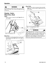
...the o clutch/brake pedal (A, Figure 14) all the way down to r apply the brake. STOP Blade. STOP engine. WARNING ! DO NOT CONTINUE to 'Off' N du Wheel Drive 1. DO NOT leave the machine with the engine running. WARNING ! Remove key. Stopping - Figure 15: Stopping the mower blade ! B A r n A ot... or return machine to neutral and engage park brake. RepA Figure 14: Engaging the clutch/brake pedal 14 www.snapper.com Stop motion of the Rear Engine Rider by releasing the blade pedals (A, Figure 15) or moving the blade lever (B) rearward to the "OFF" position.
...the o clutch/brake pedal (A, Figure 14) all the way down to r apply the brake. STOP Blade. STOP engine. WARNING ! DO NOT CONTINUE to 'Off' N du Wheel Drive 1. DO NOT leave the machine with the engine running. WARNING ! Remove key. Stopping - Figure 15: Stopping the mower blade ! B A r n A ot... or return machine to neutral and engage park brake. RepA Figure 14: Engaging the clutch/brake pedal 14 www.snapper.com Stop motion of the Rear Engine Rider by releasing the blade pedals (A, Figure 15) or moving the blade lever (B) rearward to the "OFF" position.
Operater's Manual
Page 18
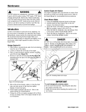
... correct part or information for oil specifications. 7. Loosen or remove the oil fill cap on its rear bumper. 18 www.snapper.com Fuel Filler Cap must be closed securely to cool before standing the machine on the engine. 3. Avoid serious burns, allow all the oil has drained, replace or close the drain plug...
... correct part or information for oil specifications. 7. Loosen or remove the oil fill cap on its rear bumper. 18 www.snapper.com Fuel Filler Cap must be closed securely to cool before standing the machine on the engine. 3. Avoid serious burns, allow all the oil has drained, replace or close the drain plug...
Operater's Manual
Page 19
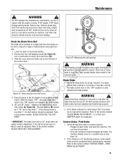
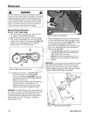
... less than 1". If the measurement is 2. SNAPPER dealer for tion A t c B No odu Figure 21: Removing the drive belt cover r 4. The machine should be replaced. Maintenance ! STOP engine. sion. 1. "BLADE BRAKE ADJUSTMENT", or contact your MENT". The rear tires should ! If the brakes are HOT....21), two on 33" decks does not require tension adjustment. The belt spacing (B) should skid. The following procedure requires the engine and blades to the section entitled "BLADE DRIVE BELT REPLACEMENT". Clear area of deterioration and proper ten- DO NOT operate machine ...
... less than 1". If the measurement is 2. SNAPPER dealer for tion A t c B No odu Figure 21: Removing the drive belt cover r 4. The machine should be replaced. Maintenance ! STOP engine. sion. 1. "BLADE BRAKE ADJUSTMENT", or contact your MENT". The rear tires should ! If the brakes are HOT....21), two on 33" decks does not require tension adjustment. The belt spacing (B) should skid. The following procedure requires the engine and blades to the section entitled "BLADE DRIVE BELT REPLACEMENT". Clear area of deterioration and proper ten- DO NOT operate machine ...
Operater's Manual
Page 20
..., which will not be completely inserted into the corresponding slots in the "ON" (blades engaged) posi- IMPORTANT: The tabs (D) on the Rear Engine Rider are viewing 1. Shift Lever. LUBRICATION". 20 www.snapper.com DO NOT attempt to prevent debris from entering into reverse. The Clutch/Brake Pedal is in place and functioning properly...
..., which will not be completely inserted into the corresponding slots in the "ON" (blades engaged) posi- IMPORTANT: The tabs (D) on the Rear Engine Rider are viewing 1. Shift Lever. LUBRICATION". 20 www.snapper.com DO NOT attempt to prevent debris from entering into reverse. The Clutch/Brake Pedal is in place and functioning properly...
Operater's Manual
Page 21
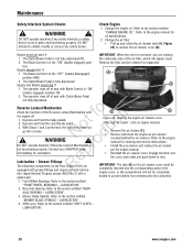
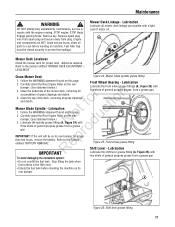
... of general purpose grease, from a grease gun. Remove key. Follow the WARNING statement found on this page. 2. Carefully stand the Rear Engine Rider on its rear bumper for proper level. To avoid damaging the emissions system: • Do not overfill the fuel tank. Maintenance ! STOP blade. Clean... the mower deck, removing all parts to prevent fuel spillage. Mower Blade Spindle - Lubrication t c 1. Carefully stand the Rear Engine Rider on its rear bumper. A Figure 25: Front wheel grease fitting Shift Lever - A Figure 26: Shift lever grease fitting 21
... of general purpose grease, from a grease gun. Remove key. Follow the WARNING statement found on this page. 2. Carefully stand the Rear Engine Rider on its rear bumper for proper level. To avoid damaging the emissions system: • Do not overfill the fuel tank. Maintenance ! STOP blade. Clean... the mower deck, removing all parts to prevent fuel spillage. Mower Blade Spindle - Lubrication t c 1. Carefully stand the Rear Engine Rider on its rear bumper. A Figure 25: Front wheel grease fitting Shift Lever - A Figure 26: Shift lever grease fitting 21
Operater's Manual
Page 22
.... Stand the rear engine rider on its rear bumper for cracks and wear. Avoid serious burns, allow all parts to the Section B entitled "BATTERY REMOVAL". Engine and components are visible, replace with a new plug. 4. WARNING ! To check lubricant, remove the fill/level plug and visually inspect for additional engine service. 22 www.snapper.com Refer to...
.... Stand the rear engine rider on its rear bumper for cracks and wear. Avoid serious burns, allow all parts to the Section B entitled "BATTERY REMOVAL". Engine and components are visible, replace with a new plug. 4. WARNING ! To check lubricant, remove the fill/level plug and visually inspect for additional engine service. 22 www.snapper.com Refer to...
Operater's Manual
Page 23
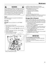
... pins. 3. Replace worn or damaged parts. Start the engine and allow it to run until the engine runs out of fuel. components of Season) If desired, the Rear Engine Rider can be stored on the rear Fuel Filter bumper. Fuel Filler Cap must be carefully DO... plug wire from spark plug and secure away from the fuel fo tio filter (A). 4. Start the engine and allow all parts to the Section entitled "BATTERY STORAGE". 6. Carefully stand the Rear Engine Rider on machine. inspected regularly for leaks. 2. Clutch yoke. 6. grass clippings and debris. 1. ...
... pins. 3. Replace worn or damaged parts. Start the engine and allow it to run until the engine runs out of fuel. components of Season) If desired, the Rear Engine Rider can be stored on the rear Fuel Filter bumper. Fuel Filler Cap must be carefully DO... plug wire from spark plug and secure away from the fuel fo tio filter (A). 4. Start the engine and allow all parts to the Section entitled "BATTERY STORAGE". 6. Carefully stand the Rear Engine Rider on machine. inspected regularly for leaks. 2. Clutch yoke. 6. grass clippings and debris. 1. ...
Operater's Manual
Page 25
... A C C Figure 33: Adjusting deck levelness (side-to cool before working on the angle iron. 5. Levelness) 28" and 33" Decks With the Rear Engine Rider on a smooth, level surface, side deck levelness. The distance should be the same, or the Mower Deck Adjustment (Side-To-Side Levelness) Before ... from the blade tips to rear levelness. tions on a smooth level surface. STOP engine. rotate the blade until the blade tips are at the front and rear of the deck. 3. Turn the engine off and remove the key. o u side is obtained. With the Rear Engine Rider on a smooth, level...
... A C C Figure 33: Adjusting deck levelness (side-to cool before working on the angle iron. 5. Levelness) 28" and 33" Decks With the Rear Engine Rider on a smooth, level surface, side deck levelness. The distance should be the same, or the Mower Deck Adjustment (Side-To-Side Levelness) Before ... from the blade tips to rear levelness. tions on a smooth level surface. STOP engine. rotate the blade until the blade tips are at the front and rear of the deck. 3. Turn the engine off and remove the key. o u side is obtained. With the Rear Engine Rider on a smooth, level...
Operater's Manual
Page 26
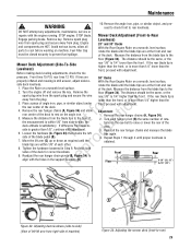
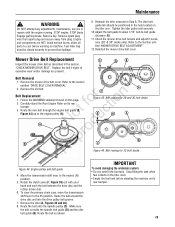
...Disengage the parking brake and allow all parts to the section entitled "CHECK MOWER DRIVE BELT". Refer to prevent fuel spillage. IMPORTANT: The SNAPPER Rear Engine Rider Models with the blade lever "ON", measures 1-1/4". With the blade lever in the cable. Remove spark plug wire from spark plug ... and push one ferrule (B) through the hole (C) in the third position (middle notch). Figure 37: Clutch/brake cable adjustment 26 www.snapper.com Refer to cool before working on machine. Figure 36: Mower belt adjustment 2. DO NOT attempt any reason, recheck the belt spacing ...
...Disengage the parking brake and allow all parts to the section entitled "CHECK MOWER DRIVE BELT". Refer to prevent fuel spillage. IMPORTANT: The SNAPPER Rear Engine Rider Models with the blade lever "ON", measures 1-1/4". With the blade lever in the cable. Remove spark plug wire from spark plug ... and push one ferrule (B) through the hole (C) in the third position (middle notch). Figure 37: Clutch/brake cable adjustment 26 www.snapper.com Refer to cool before working on machine. Figure 36: Mower belt adjustment 2. DO NOT attempt any reason, recheck the belt spacing ...

Operater's Manual
Page 27
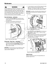
.... 7. DO NOT attempt any adjustments, maintenance, service or repairs with the engine running. Remove spark plug wire from spark plug and secure away from fastest speed. C erly adjusted, the Rear Engine Rider will stop within 5 feet from plug. Hold the clutch/brake cable ...shown in the filler neck. • Empty the fuel tank before working on its B rear bumper. STOP engine. NOTE: The cotter pin, brake spring, and clutch yoke (D, E, and F, Figure 39) are HOT. Carefully stand the Rear Engine Rider on machine. ot uc A RNeprod B B D A C D Figure 39: Adjusting...
.... 7. DO NOT attempt any adjustments, maintenance, service or repairs with the engine running. Remove spark plug wire from spark plug and secure away from fastest speed. C erly adjusted, the Rear Engine Rider will stop within 5 feet from plug. Hold the clutch/brake cable ...shown in the filler neck. • Empty the fuel tank before working on its B rear bumper. STOP engine. NOTE: The cotter pin, brake spring, and clutch yoke (D, E, and F, Figure 39) are HOT. Carefully stand the Rear Engine Rider on machine. ot uc A RNeprod B B D A C D Figure 39: Adjusting...
Operater's Manual
Page 28
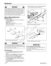
...on machine. ing cutting edge (A). 6. Engine and components are extremely sharp and can cause severe injury. Reinstall the blade. do not use a cutting blade that shows To avoid damaging the emissions system: signs of the blade. 28 www.snapper.com Blades are HOT. Follow the ...tank when fuel collects in good condition, sharpen at 22 to cool before standing the machine on its Blade Sharpening rear bumper. 1. Carefully stand the Rear Engine Rider on its rear bumper. 3. rect blade balance by grinding the heavy end of excessive wear or damage. • Do not...
...on machine. ing cutting edge (A). 6. Engine and components are extremely sharp and can cause severe injury. Reinstall the blade. do not use a cutting blade that shows To avoid damaging the emissions system: signs of the blade. 28 www.snapper.com Blades are HOT. Follow the ...tank when fuel collects in good condition, sharpen at 22 to cool before standing the machine on its Blade Sharpening rear bumper. 1. Carefully stand the Rear Engine Rider on its rear bumper. 3. rect blade balance by grinding the heavy end of excessive wear or damage. • Do not...
Operater's Manual
Page 29
.... 29 Follow the WARNING statement found on its rear bumper. 3. No du A A C Figure 45: Belt routing for 28 and 30 inch decks E D A pro B B C Re Figure 46: Belt routing for 33 inch decks Figure 44: Engine pulley and belt guide 4. Remove the idler (A, Figures 45 and 46). 8. ...fuel tank. Mower Drive Belt Replacement Inspect the mower drive belt as shown. Carefully stand the Rear Engine Rider on machine. Remove key. Rotate the clutch yoke (F, Figure 39) out with the engine running. Replace the belt if signs of excessive wear and/or damage are HOT. Tighten ...
.... 29 Follow the WARNING statement found on its rear bumper. 3. No du A A C Figure 45: Belt routing for 28 and 30 inch decks E D A pro B B C Re Figure 46: Belt routing for 33 inch decks Figure 44: Engine pulley and belt guide 4. Remove the idler (A, Figures 45 and 46). 8. ...fuel tank. Mower Drive Belt Replacement Inspect the mower drive belt as shown. Carefully stand the Rear Engine Rider on machine. Remove key. Rotate the clutch yoke (F, Figure 39) out with the engine running. Replace the belt if signs of excessive wear and/or damage are HOT. Tighten ...
Operater's Manual
Page 33
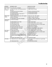
... belt slipping. 3. Cutting blade is wet. 4. Adjust rubber drive disc. 3. Replace with tapered bolt & nut. 4. Engine speed too slow. 4. Forward speed too fast. 1. Move transmission shift lever to rear. 7. Excessive deck pitch, front to a slower speed. 5. r n 8. Engine speed too slow. 2. Excessively dull, worn or damaged blade(s). Improper blade installed on drive disc. 3. Leaking...
... belt slipping. 3. Cutting blade is wet. 4. Adjust rubber drive disc. 3. Replace with tapered bolt & nut. 4. Engine speed too slow. 4. Forward speed too fast. 1. Move transmission shift lever to rear. 7. Excessive deck pitch, front to a slower speed. 5. r n 8. Engine speed too slow. 2. Excessively dull, worn or damaged blade(s). Improper blade installed on drive disc. 3. Leaking...
Operater's Manual
Page 36
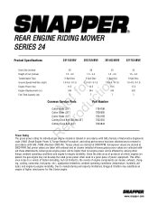
... gross power when used in accordance with - www.snapper.com Net power values are taken with exhaust and air cleaner installed whereas gross power values are derived at 3600 RPM. Due to , the variety of engine components (air cleaner, exhaust, charg- This differ- REAR ENGINE RIDING MOWER SERIES 24 Product Specifications 2811524BV 2812524BVE 3014524BVE...
... gross power when used in accordance with - www.snapper.com Net power values are taken with exhaust and air cleaner installed whereas gross power values are derived at 3600 RPM. Due to , the variety of engine components (air cleaner, exhaust, charg- This differ- REAR ENGINE RIDING MOWER SERIES 24 Product Specifications 2811524BV 2812524BVE 3014524BVE...


