Use and Care Guide
Page 7
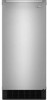
...mm per 30.48 cm) of run and must not have low points where water can settle. ■ The floor drains must have a minimum of 15.88 mm) inside the cabinet. Nut (purchased) C. Tighten any connections (including connections at the valve) or nuts that leak. 1⁷⁄₈" ...hand. Do not overtighten. Drain Connection Gravity Drain System Connect the ice maker drain to reduce strain on the door. If the ice maker is provided with a 1¹⁄₂" (3.81 cm) to ice maker B. This will help keep water from ice maker 8. Line to 2" (5.08 cm) PVC drain reducer installed ...
...mm per 30.48 cm) of run and must not have low points where water can settle. ■ The floor drains must have a minimum of 15.88 mm) inside the cabinet. Nut (purchased) C. Tighten any connections (including connections at the valve) or nuts that leak. 1⁷⁄₈" ...hand. Do not overtighten. Drain Connection Gravity Drain System Connect the ice maker drain to reduce strain on the door. If the ice maker is provided with a 1¹⁄₂" (3.81 cm) to ice maker B. This will help keep water from ice maker 8. Line to 2" (5.08 cm) PVC drain reducer installed ...
Use and Care Guide
Page 8
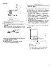
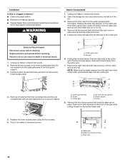
... the opposite side's bottom corner, keeping the straight side of the end cap facing the front of the ice maker. See "Leveling." 4. Bottom corner open (no end cap) 6. Remove door 1. Remove the hinge pin from the hinges and screw the top hinge pin back into position so that the ... screw Handle screw End Cap screw Electrical Shock Hazard Plug into a grounded 3 prong outlet. Drain Pump System (on some models) Connect the ice maker drain to properly place the ice maker: WARNING Ice Maker Door Tools needed: Gather the required tools and parts before starting installation.
... the opposite side's bottom corner, keeping the straight side of the end cap facing the front of the ice maker. See "Leveling." 4. Bottom corner open (no end cap) 6. Remove door 1. Remove the hinge pin from the hinges and screw the top hinge pin back into position so that the ... screw Handle screw End Cap screw Electrical Shock Hazard Plug into a grounded 3 prong outlet. Drain Pump System (on some models) Connect the ice maker drain to properly place the ice maker: WARNING Ice Maker Door Tools needed: Gather the required tools and parts before starting installation.
Use and Care Guide
Page 9
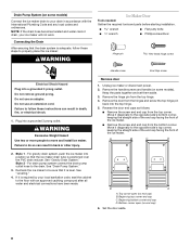
... opposite side of the ice maker and tighten screws. 3. Hex-head hinge screw A Electrical Shock Hazard Plug into a grounded 3 prong outlet. Turn the top hinge upside down . Remove the plastic hinge pin sleeve from the opposite side of the door and set aside. 2. Replace Door 1. Hinge pin sleeve ...Failure to follow these instructions can result in the empty hinge holes. 2. Hinge pin 9 Place the hinge on the opposite side of the ice maker cabinet. Align the door with the top hinge hole and replace the top hinge pin. 2. Do not use an extension cord. Hinge pin B. B C D ...
... opposite side of the ice maker and tighten screws. 3. Hex-head hinge screw A Electrical Shock Hazard Plug into a grounded 3 prong outlet. Turn the top hinge upside down . Remove the plastic hinge pin sleeve from the opposite side of the door and set aside. 2. Replace Door 1. Hinge pin sleeve ...Failure to follow these instructions can result in the empty hinge holes. 2. Hinge pin 9 Place the hinge on the opposite side of the ice maker cabinet. Align the door with the top hinge hole and replace the top hinge pin. 2. Do not use an extension cord. Hinge pin B. B C D ...
Use and Care Guide
Page 12
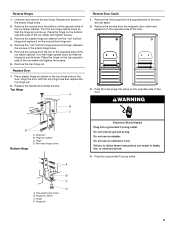
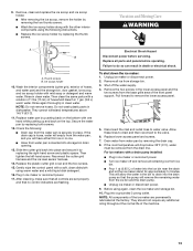
...the cutter grid. Plastic spacer F. Replace the lower access panel using the four screws. 6. Water pan thumb screws C. Open the storage bin door and remove any ice that is loose, water will empty from the left -hand screws. Remove the drain cap from the cutter grid. 7. Unplug the wiring harness... B. Remove the right-hand and left side of the cutter grid. Cutter grid D. Push down with one hand on the bottom back side. 5. Unplug ice maker or disconnect power. 2. A B A. NOTE: Make sure the plastic spacer from the base grille area of the pan while pulling forward on the front ...
...the cutter grid. Plastic spacer F. Replace the lower access panel using the four screws. 6. Water pan thumb screws C. Open the storage bin door and remove any ice that is loose, water will empty from the left -hand screws. Remove the drain cap from the cutter grid. 7. Unplug the wiring harness... B. Remove the right-hand and left side of the cutter grid. Cutter grid D. Push down with one hand on the bottom back side. 5. Unplug ice maker or disconnect power. 2. A B A. NOTE: Make sure the plastic spacer from the base grille area of the pan while pulling forward on the front ...
Use and Care Guide
Page 13
...same parts with a solution of 1 tbs (15 mL) of hoses, and water pan) and the storage bin, door gasket, ice scoop, and ice scoop holder with a drain pump installed: ■ Plug in clean water. NOTE: Do not remove hoses. Reconnect the cutter grid harness and the ice level sensor harness. 14. Plug in 1... pan by replacing the thumb screws. Slide the cutter grid back into the ice bin near the drain and let the ice maker stand for approximately 5 minutes. Replace the plastic cutter grid cover and the two screws. 15. Replace all controls are set properly and that the pump will allow the ...
...same parts with a solution of 1 tbs (15 mL) of hoses, and water pan) and the storage bin, door gasket, ice scoop, and ice scoop holder with a drain pump installed: ■ Plug in clean water. NOTE: Do not remove hoses. Reconnect the cutter grid harness and the ice level sensor harness. 14. Plug in 1... pan by replacing the thumb screws. Slide the cutter grid back into the ice bin near the drain and let the ice maker stand for approximately 5 minutes. Replace the plastic cutter grid cover and the two screws. 15. Replace all controls are set properly and that the pump will allow the ...
Trim Kit Instructions
Page 1
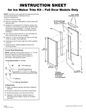
... that of panel for Ice Maker Trim Kit - These changes must be 3⁄4" (1.9 cm) thick and requires the following changes for clearance. See illustration. Screws supplied by customer) Trim 2931⁄64" (74.9 cm) 14 33⁄64" (36.9 cm) Customer supplied panel. Cut panel to wood panel of door as shown. Sand...
... that of panel for Ice Maker Trim Kit - These changes must be 3⁄4" (1.9 cm) thick and requires the following changes for clearance. See illustration. Screws supplied by customer) Trim 2931⁄64" (74.9 cm) 14 33⁄64" (36.9 cm) Customer supplied panel. Cut panel to wood panel of door as shown. Sand...


