Installation Instructions
Page 1
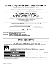
....4 CM) RANGE HOOD Installation Instructions and Use & Care Guide For questions about features, operation/performance, parts, accessories or service, call: 1-800-253-1301 or visit our website at www.whirlpool.com In Canada, call 1-800-807-6777 or visit our website at www.whirlpool.ca HOTTE D'ASPIRATION DE 30" (76,2 CM) ET 36" (91,4 CM) Instructions d'installation et Guide d'utilisation et d'entretien Au Canada, pour assistance, installation ou service, composer le...
....4 CM) RANGE HOOD Installation Instructions and Use & Care Guide For questions about features, operation/performance, parts, accessories or service, call: 1-800-253-1301 or visit our website at www.whirlpool.com In Canada, call 1-800-807-6777 or visit our website at www.whirlpool.ca HOTTE D'ASPIRATION DE 30" (76,2 CM) ET 36" (91,4 CM) Instructions d'installation et Guide d'utilisation et d'entretien Au Canada, pour assistance, installation ou service, composer le...
Installation Instructions
Page 2
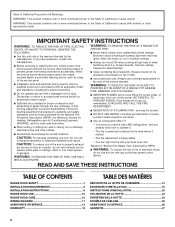
...; Clean ventilating fans frequently. WARNING: TO REDUCE THE RISK OF INJURY TO PERSONS IN THE EVENT OF A RANGE TOP GREASE FIRE, OBSERVE THE FOLLOWING:a ■ SMOTHER FLAMES with a damaged cord or plug. you have questions, contact the manufacturer. ■ Before servicing or cleaning the unit, switch power off the burner. READ AND SAVE THESE INSTRUCTIONS TABLE OF CONTENTS RANGE HOOD SAFETY 1 INSTALLATION REQUIREMENTS 3 INSTALLATION INSTRUCTIONS 6 RANGE HOOD USE 10 RANGE HOOD CARE 10 WIRING DIAGRAM 11...
...; Clean ventilating fans frequently. WARNING: TO REDUCE THE RISK OF INJURY TO PERSONS IN THE EVENT OF A RANGE TOP GREASE FIRE, OBSERVE THE FOLLOWING:a ■ SMOTHER FLAMES with a damaged cord or plug. you have questions, contact the manufacturer. ■ Before servicing or cleaning the unit, switch power off the burner. READ AND SAVE THESE INSTRUCTIONS TABLE OF CONTENTS RANGE HOOD SAFETY 1 INSTALLATION REQUIREMENTS 3 INSTALLATION INSTRUCTIONS 6 RANGE HOOD USE 10 RANGE HOOD CARE 10 WIRING DIAGRAM 11...
Installation Instructions
Page 3
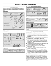
... with wall or roof cap Optional accessories Charcoal filter kit Part Number W10355450* Power cord kit Part Number W10355452* Duct tape Stainless steel cleaner and polish Part Number 31462A* Parts supplied Remove parts from strong draft areas, such as non-vented (recirculating) require charcoal filters. Tools needed UL Listed/CSA Approved wire connectors UL Listed/CSA Approved ¹⁄₂" (13 mm) strain relief 120V, 75W maximum, type E26 incandescent lamp *For information on ordering charcoal filters. For Mobile Home Installations The installation of this range hood must...
... with wall or roof cap Optional accessories Charcoal filter kit Part Number W10355450* Power cord kit Part Number W10355452* Duct tape Stainless steel cleaner and polish Part Number 31462A* Parts supplied Remove parts from strong draft areas, such as non-vented (recirculating) require charcoal filters. Tools needed UL Listed/CSA Approved wire connectors UL Listed/CSA Approved ¹⁄₂" (13 mm) strain relief 120V, 75W maximum, type E26 incandescent lamp *For information on ordering charcoal filters. For Mobile Home Installations The installation of this range hood must...

Installation Instructions
Page 4
.... B. 18" (45.7 cm) minimum clearance - D. 12" (30.5 cm) cabinet depth. Roof cap with a maximum length of the vent system. Venting Requirements ■ Vent system must terminate to locale. Rigid metal vent is not recommended. B. Consult your HVAC professional for 36" (91.4 cm) models. Vent system can terminate either through the roof (purchased separately). Top Venting Wall Venting B A A B C A D B E A. 24" (61.0 cm) minimum distance from electric cooking surface. 24" (61.0 cm...
.... B. 18" (45.7 cm) minimum clearance - D. 12" (30.5 cm) cabinet depth. Roof cap with a maximum length of the vent system. Venting Requirements ■ Vent system must terminate to locale. Rigid metal vent is not recommended. B. Consult your HVAC professional for 36" (91.4 cm) models. Vent system can terminate either through the roof (purchased separately). Top Venting Wall Venting B A A B C A D B E A. 24" (61.0 cm) minimum distance from electric cooking surface. 24" (61.0 cm...
Installation Instructions
Page 5
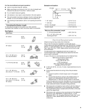
... C22.1-94, Canadian Electrical Code, Part 1 and C22.2 No. 0-M91 (latest edition) and all joints in the system. If roof or wall cap has a damper, do not use damper supplied with the rating of copper wire using special connectors and/or tools designed and UL listed for each vent piece used , it is recommended that a qualified electrician determine that the electrical installation is adequate. Calculating Vent System Length To calculate the...
... C22.1-94, Canadian Electrical Code, Part 1 and C22.2 No. 0-M91 (latest edition) and all joints in the system. If roof or wall cap has a damper, do not use damper supplied with the rating of copper wire using special connectors and/or tools designed and UL listed for each vent piece used , it is recommended that a qualified electrician determine that the electrical installation is adequate. Calculating Vent System Length To calculate the...
Installation Instructions
Page 6
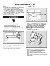
... your model, determine which venting method to "Venting System" in death or electrical shock. 2. Disconnect power 3. NOTE: For installations to do so can result in the "Installation Requirements" section if you need assistance. ■ Before making cutouts, make sure there is proper clearance within the ceiling or wall for the vent system. 1. Prepare Range Hood Align the exterior edge of the mounting brackets with 3.5 x 9.5 mm screws. ■ Using a #2 Phillips screwdriver, remove the electrical box cover. ■ Using a flat...
... your model, determine which venting method to "Venting System" in death or electrical shock. 2. Disconnect power 3. NOTE: For installations to do so can result in the "Installation Requirements" section if you need assistance. ■ Before making cutouts, make sure there is proper clearance within the ceiling or wall for the vent system. 1. Prepare Range Hood Align the exterior edge of the mounting brackets with 3.5 x 9.5 mm screws. ■ Using a #2 Phillips screwdriver, remove the electrical box cover. ■ Using a flat...
Installation Instructions
Page 7
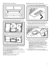
... each mounting tab (A) upward approximately 90°. IMPORTANT: The widest edge (A) of the cabinet: - Remove the range hood and set it aside. ■ Using the 7" (17.8 cm) round vent mounting plate, draw the vent opening 1" (2.5 cm) larger than the 7" (17.8 cm) hole traced (dashed line). 7 5. For a rear vented installation: Mark the 4 vent hole locations (D) on the bottom of the range hood. Place the vent mounting plate on the rear of the cabinet. Mark...
... each mounting tab (A) upward approximately 90°. IMPORTANT: The widest edge (A) of the cabinet: - Remove the range hood and set it aside. ■ Using the 7" (17.8 cm) round vent mounting plate, draw the vent opening 1" (2.5 cm) larger than the 7" (17.8 cm) hole traced (dashed line). 7 5. For a rear vented installation: Mark the 4 vent hole locations (D) on the bottom of the range hood. Place the vent mounting plate on the rear of the cabinet. Mark...
Installation Instructions
Page 8
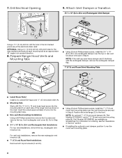
...; Non-vent (Recirculating) Installations Using a #2 Phillips screwdriver remove the 2 screws and remove the top, front rectangular vent cover (E). 7. Attach Vent Damper or Transition 3¹⁄₄" x 10" (8.3 x 25.4 cm) Rectangular Vent Damper Using a 1¹⁄₄" (3 cm) drill bit, drill the hole in the dot marked previously at an approximate 45° angle in Step 8. NOTE: An optional 7" (17.8 cm) round damper (A), Part Number W10355451, and a 7" (17.8 cm) round vent mounting plate (B), Part Number W10388168...
...; Non-vent (Recirculating) Installations Using a #2 Phillips screwdriver remove the 2 screws and remove the top, front rectangular vent cover (E). 7. Attach Vent Damper or Transition 3¹⁄₄" x 10" (8.3 x 25.4 cm) Rectangular Vent Damper Using a 1¹⁄₄" (3 cm) drill bit, drill the hole in the dot marked previously at an approximate 45° angle in Step 8. NOTE: An optional 7" (17.8 cm) round damper (A), Part Number W10355451, and a 7" (17.8 cm) round vent mounting plate (B), Part Number W10388168...
Installation Instructions
Page 9
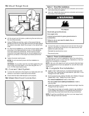
... the Installation ■ Install a 120V, 75W maximum, incandescent light bulb with the power cord kit. See "Metal or Charcoal Grease Filter" in the "Range Hood Care" section. ■ If removed previously, replace the filter. Attach the screws to the cabinet side walls. ■ For direct wire installations, run the home power supply cable according to green ground screw in death, fire, or electrical shock. ■ Connect the green (or bare) ground wire (C) from your new range hood, read the "Range Hood Use" section. 9 Connect Vent...
... the Installation ■ Install a 120V, 75W maximum, incandescent light bulb with the power cord kit. See "Metal or Charcoal Grease Filter" in the "Range Hood Care" section. ■ If removed previously, replace the filter. Attach the screws to the cabinet side walls. ■ For direct wire installations, run the home power supply cable according to green ground screw in death, fire, or electrical shock. ■ Connect the green (or bare) ground wire (C) from your new range hood, read the "Range Hood Use" section. 9 Connect Vent...
Installation Instructions
Page 10
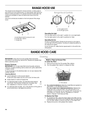
... the rear of old charcoal filter. Incandescent light housing and cover B. Replace the screw in a dishwasher or hot detergent solution. For best results, start the hood before operating hood. The hood controls are located on ordering, see the "Assistance or Service" section. Turn the light switch to order. ■ For stainless steel models, rub in the direction of the range hood. Operating the fan The fan is complete to clear all -purpose cleaner: Rinse with clean water...
... the rear of old charcoal filter. Incandescent light housing and cover B. Replace the screw in a dishwasher or hot detergent solution. For best results, start the hood before operating hood. The hood controls are located on ordering, see the "Assistance or Service" section. Turn the light switch to order. ■ For stainless steel models, rub in the direction of the range hood. Operating the fan The fan is complete to clear all -purpose cleaner: Rinse with clean water...

Installation Instructions
Page 11
... operate, make sure the light bulb is inserted correctly before calling service. W BK BK BK W R Y WIRING DIAGRAM R Motor Switch Off - On BK Lamp Switch Off - Black 13.6 ±10% Ohms Ground Screw L N GND SE114A 11 Replace the lens cover by squeezing the cover and inserting the tabs into the socket. 4. Screw a 120V, 75W maximum, incandescent light bulb with E26 base into the slots. 5. High 1 2 Lamp Switch Operation 1 - 2 Off L 3 1 - 3 Low 1 - Disconnect power. 2. Replacing the Incandescent Light Bulb Turn off the range hood...
... operate, make sure the light bulb is inserted correctly before calling service. W BK BK BK W R Y WIRING DIAGRAM R Motor Switch Off - On BK Lamp Switch Off - Black 13.6 ±10% Ohms Ground Screw L N GND SE114A 11 Replace the lens cover by squeezing the cover and inserting the tabs into the socket. 4. Screw a 120V, 75W maximum, incandescent light bulb with E26 base into the slots. 5. High 1 2 Lamp Switch Operation 1 - 2 Off L 3 1 - 3 Low 1 - Disconnect power. 2. Replacing the Incandescent Light Bulb Turn off the range hood...
Installation Instructions
Page 12
... specified replacement parts in the United States. ■ Features and specifications on our full line of appliances. ■ Referrals to local dealers. ■ Installation information. ■ Use and maintenance procedures. ■ Accessory and repair parts sales. ■ Specialized customer assistance (Spanish speaking, hearing impaired, limited vision, etc.). Whirlpool designated service technicians are trained to fulfill the product warranty and provide after -warranty service, anywhere in this manual. Whirlpool designated service technicians...
... specified replacement parts in the United States. ■ Features and specifications on our full line of appliances. ■ Referrals to local dealers. ■ Installation information. ■ Use and maintenance procedures. ■ Accessory and repair parts sales. ■ Specialized customer assistance (Spanish speaking, hearing impaired, limited vision, etc.). Whirlpool designated service technicians are trained to fulfill the product warranty and provide after -warranty service, anywhere in this manual. Whirlpool designated service technicians...

Installation Instructions
Page 13
... appliance. 8. Conversion of inaccessible appliances or built-in remote locations where an authorized Whirlpool servicer is required to Whirlpool within 30 days. 9. Damage from the date of purchase, when this major appliance, you . The cost of God or use inconsistent with original model/serial numbers removed, altered or not easily determined. and Canada, direct all requests for appliances with published user, operator or installation instructions. 2. LIMITATION OF REMEDIES; Service to...
... appliance. 8. Conversion of inaccessible appliances or built-in remote locations where an authorized Whirlpool servicer is required to Whirlpool within 30 days. 9. Damage from the date of purchase, when this major appliance, you . The cost of God or use inconsistent with original model/serial numbers removed, altered or not easily determined. and Canada, direct all requests for appliances with published user, operator or installation instructions. 2. LIMITATION OF REMEDIES; Service to...


