
Hardware Installation Guide
Page 14
... DUPLX SPEED MODE Catalyst 2960-24-S Switch Front Panel Catalyst 2960 Series SI 204632 1 1 10/100 ports The 10/100 ports on . Front Panel Description Chapter 1 Product Overview Front Panel Description These sections describe the switch front panels: • Catalyst 2960 Switch 24- and 48-Port Switches These sections describe the Catalyst 2960 24- and 48-Port Switches, page 1-4 • Catalyst 2960 8-Port Switches, page 1-9 • 10...
... DUPLX SPEED MODE Catalyst 2960-24-S Switch Front Panel Catalyst 2960 Series SI 204632 1 1 10/100 ports The 10/100 ports on . Front Panel Description Chapter 1 Product Overview Front Panel Description These sections describe the switch front panels: • Catalyst 2960 Switch 24- and 48-Port Switches These sections describe the Catalyst 2960 24- and 48-Port Switches, page 1-4 • Catalyst 2960 8-Port Switches, page 1-9 • 10...

Hardware Installation Guide
Page 15
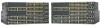
...type for these ports. See Figure 1-2 and Figure 1-3. Figure 1-4 Catalyst 2960-48TT-S Switch Front Panel Catalyst 2960 Series SI 271431 1 2 1 10/100 ports 2 10/100/1000 ports OL-7075-09 Catalyst 2960 Switch Hardware Installation Guide 1-5 For more information about the dual-purpose port... Port" section on . The See Figure 1-4. Figure 1-2 SYST STAT DUPLX SPEED MODE Catalyst 2960-24TC-S Switch Front Panel Catalyst 2960 Series SI 204631 1 2 1 10/100 ports 2 Dual-purpose ports Figure 1-3 Catalyst 2960-48TC-S Switch Front Panel SYST STAT DUPLX SPEED MODE 1 2 3 4 5 6 7 8 9...
...type for these ports. See Figure 1-2 and Figure 1-3. Figure 1-4 Catalyst 2960-48TT-S Switch Front Panel Catalyst 2960 Series SI 271431 1 2 1 10/100 ports 2 10/100/1000 ports OL-7075-09 Catalyst 2960 Switch Hardware Installation Guide 1-5 For more information about the dual-purpose port... Port" section on . The See Figure 1-4. Figure 1-2 SYST STAT DUPLX SPEED MODE Catalyst 2960-24TC-S Switch Front Panel Catalyst 2960 Series SI 204631 1 2 1 10/100 ports 2 Dual-purpose ports Figure 1-3 Catalyst 2960-48TC-S Switch Front Panel SYST STAT DUPLX SPEED MODE 1 2 3 4 5 6 7 8 9...

Hardware Installation Guide
Page 16
... RPS STAT DUPLX SPEED PoE MODE Catalyst 2960-24PC-L Switch Front Panel 1 2 1X 3 4 5 6 7 8 9 10 11 12 13 14 15 16 17 18 19 20 21 22 23 24 11X 13X 23X Catalyst 2960 Series PoE-24 2X POWER OVER ETHERNET 12X... 14X 1 2 24X 204641 1 2 1 10/100 PoE ports 2 Dual-purpose ports Figure 1-6 Catalyst 2960-24PC-S Switch Front Panel 206731 1 2 1 10/100 PoE ports 2 Dual-purpose ports Figure 1-7 Catalyst 2960-24LC-S Switch Front Panel 206730 1 2 3 1 10/100 PoE ports 3 Dual-purpose ports 2 10/100 ports Catalyst 2960 Switch...
... RPS STAT DUPLX SPEED PoE MODE Catalyst 2960-24PC-L Switch Front Panel 1 2 1X 3 4 5 6 7 8 9 10 11 12 13 14 15 16 17 18 19 20 21 22 23 24 11X 13X 23X Catalyst 2960 Series PoE-24 2X POWER OVER ETHERNET 12X... 14X 1 2 24X 204641 1 2 1 10/100 PoE ports 2 Dual-purpose ports Figure 1-6 Catalyst 2960-24PC-S Switch Front Panel 206731 1 2 1 10/100 PoE ports 2 Dual-purpose ports Figure 1-7 Catalyst 2960-24LC-S Switch Front Panel 206730 1 2 3 1 10/100 PoE ports 3 Dual-purpose ports 2 10/100 ports Catalyst 2960 Switch...
Hardware Installation Guide
Page 17
...See Figure 1-10, Figure 1-11, and Figure 1-12. 204642 Figure 1-10 Catalyst 2960-24LT-L Switch Front Panel SYST RPS STAT DUPLX SPEED PoE MODE 1 2 1X 34 5 6 7 8 9 10 11 12 13 14 15 16 17 18 19 20 21 22 23 24 Catalyst 2960 Series PoE-8 11X 13X 23X 2X POWER OVER ETHERNET 12X 14X 1 2 24X... 1 2 3 1 10/100 PoE ports 3 10/100/1000 uplink ports 2 10/100 ports Figure 1-11 Catalyst 2960-24TT-L Switch Front Panel 204607 SYST RPS STAT DUPLX SPEED MODE 1 2 1 ...
...See Figure 1-10, Figure 1-11, and Figure 1-12. 204642 Figure 1-10 Catalyst 2960-24LT-L Switch Front Panel SYST RPS STAT DUPLX SPEED PoE MODE 1 2 1X 34 5 6 7 8 9 10 11 12 13 14 15 16 17 18 19 20 21 22 23 24 Catalyst 2960 Series PoE-8 11X 13X 23X 2X POWER OVER ETHERNET 12X 14X 1 2 24X... 1 2 3 1 10/100 PoE ports 3 10/100/1000 uplink ports 2 10/100 ports Figure 1-11 Catalyst 2960-24TT-L Switch Front Panel 204607 SYST RPS STAT DUPLX SPEED MODE 1 2 1 ...

Hardware Installation Guide
Page 18
... 40 41 42 43 44 45 46 47 48 Catalyst 2960 Series PoE-48 11X 13X 23X 24X 35X 37X 47X 1 2 12X 14X 24X 26X 36X 38X 3 4 48X 1 2 205644 1 10/100 PoE ports 2 10/100/1000 uplink ports 3 SFP module slots Figure 1-14 Catalyst 2960-48PST-S Switch Front Panel 3 206732 1 2 1 10/100 PoE... 1) is above the second member (port 2), port 3 is above port 4, and so on the switch are numbered 21 to 24 on the Catalyst 2960G-24TC-L switch and 45 to 48 on . Catalyst 2960 Switch Hardware Installation Guide 1-8 OL-7075-09 The SFP module slots are PoE ports. Use the software to set...
... 40 41 42 43 44 45 46 47 48 Catalyst 2960 Series PoE-48 11X 13X 23X 24X 35X 37X 47X 1 2 12X 14X 24X 26X 36X 38X 3 4 48X 1 2 205644 1 10/100 PoE ports 2 10/100/1000 uplink ports 3 SFP module slots Figure 1-14 Catalyst 2960-48PST-S Switch Front Panel 3 206732 1 2 1 10/100 PoE... 1) is above the second member (port 2), port 3 is above port 4, and so on the switch are numbered 21 to 24 on the Catalyst 2960G-24TC-L switch and 45 to 48 on . Catalyst 2960 Switch Hardware Installation Guide 1-8 OL-7075-09 The SFP module slots are PoE ports. Use the software to set...

Hardware Installation Guide
Page 19
... 12X 16X 18X 12X 32X 34X 46X 1 Catalyst 2960 SERIES 46 47 48 2 1 10/100/1000 ports 2 Dual-purpose ports 204611 Catalyst 2960 8-Port Switches These sections describe the Catalyst 2960 8-port switches: • Catalyst 2960PD-8TT-L Switch, page 1-9 • Catalyst 2960-8TC-S, Catalyst 2960-8TC-L, and Catalyst 2960G-8TC -L Switches, page 1-10 Catalyst 2960PD-8TT-L Switch The Catalyst 2960PD-8TT-L (Figure 1-17) switch front panel has a console port, eight 10...
... 12X 16X 18X 12X 32X 34X 46X 1 Catalyst 2960 SERIES 46 47 48 2 1 10/100/1000 ports 2 Dual-purpose ports 204611 Catalyst 2960 8-Port Switches These sections describe the Catalyst 2960 8-port switches: • Catalyst 2960PD-8TT-L Switch, page 1-9 • Catalyst 2960-8TC-S, Catalyst 2960-8TC-L, and Catalyst 2960G-8TC -L Switches, page 1-10 Catalyst 2960PD-8TT-L Switch The Catalyst 2960PD-8TT-L (Figure 1-17) switch front panel has a console port, eight 10...

Hardware Installation Guide
Page 20
... port 3 Dual-purpose port 2 10/100/100 ports Catalyst 2960 Series SI 3 Figure 1-19 Catalyst 2960-8TC-L Switch Front Panel SYST STAT DPLX SPD MODE CONSOLE 1x 2x 3x 4x 5x 6x 7x 8x Catalyst 2960 Series 1 204627 1 2 3 1 Console port 3 Dual-purpose port 2 10/100/100 ports Figure 1-20 Catalyst 2960G-8TC-L Switch Front Panel SYST STAT DPLX SPD MODE CONSOLE...
... port 3 Dual-purpose port 2 10/100/100 ports Catalyst 2960 Series SI 3 Figure 1-19 Catalyst 2960-8TC-L Switch Front Panel SYST STAT DPLX SPD MODE CONSOLE 1x 2x 3x 4x 5x 6x 7x 8x Catalyst 2960 Series 1 204627 1 2 3 1 Console port 3 Dual-purpose port 2 10/100/100 ports Figure 1-20 Catalyst 2960G-8TC-L Switch Front Panel SYST STAT DPLX SPD MODE CONSOLE...
Hardware Installation Guide
Page 24
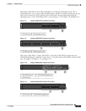
... 1x 2x 3x 4x 5x 6x 7x 8x CONSOLE MODE Catalyst 2960 Series 1 PoE INPUT 1 204644 Figure 1-22 1 Connecting Through an External AC Power Adapter 48V , 0.3 A 270433 LEDs 1 Power adapter port You can use the CLI to configure and to monitor individual switches and switch clusters. All LEDs are visible through the GUI management applications...
... 1x 2x 3x 4x 5x 6x 7x 8x CONSOLE MODE Catalyst 2960 Series 1 PoE INPUT 1 204644 Figure 1-22 1 Connecting Through an External AC Power Adapter 48V , 0.3 A 270433 LEDs 1 Power adapter port You can use the CLI to configure and to monitor individual switches and switch clusters. All LEDs are visible through the GUI management applications...

Hardware Installation Guide
Page 38
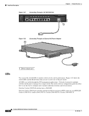
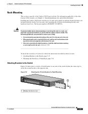
... 1006 Catalyst 2960 Switch Hardware Installation Guide 2-6 OL-7075-09 After a successful POST, disconnect the power cord from the bottom to ensure that the switch functions properly. The illustrations in the "Installing the Switch" section on , it is provided with the heaviest component at the bottom of the rack if it begins the POST, a series of...
... 1006 Catalyst 2960 Switch Hardware Installation Guide 2-6 OL-7075-09 After a successful POST, disconnect the power cord from the bottom to ensure that the switch functions properly. The illustrations in the "Installing the Switch" section on , it is provided with the heaviest component at the bottom of the rack if it begins the POST, a series of...

Hardware Installation Guide
Page 49
... from the SFP module. Step 2 Disconnect the LC connector from contamination and ambient light. and 48-Port Switches) Installing and Removing SFP Modules Figure 2-15 Installing an SFP Module into an SFP Module Slot 1X Catalyst 2960 Series SI 11X 1 2 204639 1 1 SFP module Step 5 Remove the dust plugs from the fiber-optic cable until...
... from the SFP module. Step 2 Disconnect the LC connector from contamination and ambient light. and 48-Port Switches) Installing and Removing SFP Modules Figure 2-15 Installing an SFP Module into an SFP Module Slot 1X Catalyst 2960 Series SI 11X 1 2 204639 1 1 SFP module Step 5 Remove the dust plugs from the fiber-optic cable until...
Hardware Installation Guide
Page 59
... upstream PoE switch. The other Catalyst 2960 switches, see Chapter 2, "Switch Installation (24- This section describes these installation procedures: • Desk- Chapter 3 Switch Installation (8-Port Switches) Verifying Switch Operation Installing the Catalyst 2960 8-port switches in a 19-inch rack requires an optional bracket kit that it begins the POST, a series of tests that runs automatically to ensure that adapter from Cisco. You can...
... upstream PoE switch. The other Catalyst 2960 switches, see Chapter 2, "Switch Installation (24- This section describes these installation procedures: • Desk- Chapter 3 Switch Installation (8-Port Switches) Verifying Switch Operation Installing the Catalyst 2960 8-port switches in a 19-inch rack requires an optional bracket kit that it begins the POST, a series of tests that runs automatically to ensure that adapter from Cisco. You can...

Hardware Installation Guide
Page 68
... installation. Power on page 2-20 to Appendix C, "Configuring the Switch with a Magnet 2 Catalyst 2960 Series 1 204636 8 x 7 x 6 x 5 x 4 x 3 x STAT DPLX SPD 1 x 2 x CONSOLE SYST 3 1 Metal surface 3 Switch 2 Magnet Step 2 Mount the magnet and switch on page 3-5. 2. After the switch is specific to complete the installation: 1. Installing the Switch Chapter 3 Switch Installation (8-Port Switches) Magnet Mounting This section is attached to the mounting magnet...
... installation. Power on page 2-20 to Appendix C, "Configuring the Switch with a Magnet 2 Catalyst 2960 Series 1 204636 8 x 7 x 6 x 5 x 4 x 3 x STAT DPLX SPD 1 x 2 x CONSOLE SYST 3 1 Metal surface 3 Switch 2 Magnet Step 2 Mount the magnet and switch on page 3-5. 2. After the switch is specific to complete the installation: 1. Installing the Switch Chapter 3 Switch Installation (8-Port Switches) Magnet Mounting This section is attached to the mounting magnet...
Hardware Installation Guide
Page 69
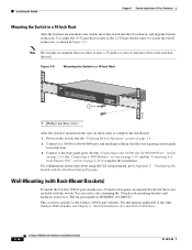
... SPD MODE CONSOLE 1x 2x 3x 4x 5x 6x 7x 8x Catalyst 2960 Series 1 1 1 Phillips flat-head screw 204637 OL-7075-09 Catalyst 2960 Switch Hardware Installation Guide 3-15 Installing the Catalyst 2960 8-port switches in a partially filled rack, load the rack from Cisco. Chapter 3 Switch Installation (8-Port Switches) Installing the Switch Rack-Mounting This section is RCKMNT-19-CMPCT=. For information applicable...
... SPD MODE CONSOLE 1x 2x 3x 4x 5x 6x 7x 8x Catalyst 2960 Series 1 1 1 Phillips flat-head screw 204637 OL-7075-09 Catalyst 2960 Switch Hardware Installation Guide 3-15 Installing the Catalyst 2960 8-port switches in a partially filled rack, load the rack from Cisco. Chapter 3 Switch Installation (8-Port Switches) Installing the Switch Rack-Mounting This section is RCKMNT-19-CMPCT=. For information applicable...
Hardware Installation Guide
Page 70
... 12-24 pan-slotted screws to the other Catalyst 2960 switches, see Chapter 2, "Switch Installation (24- You can order a kit containing the 19-inch rack-mounting brackets and hardware from Cisco. and 48-Port Switches)." 3-16 Catalyst 2960 Switch Hardware Installation Guide OL-7075-09 Power on ... 6x 7x 8x 1 Catalyst 2960 Series 1 204638 1 Phillips machine screws After the switch is not included with the CLI-Based Setup Program." Connect to complete the installation: 1. Wall-Mounting (with Rack-Mount Brackets) To install the Catalyst 2960 8-port switches in a 19-inch ...
... 12-24 pan-slotted screws to the other Catalyst 2960 switches, see Chapter 2, "Switch Installation (24- You can order a kit containing the 19-inch rack-mounting brackets and hardware from Cisco. and 48-Port Switches)." 3-16 Catalyst 2960 Switch Hardware Installation Guide OL-7075-09 Power on ... 6x 7x 8x 1 Catalyst 2960 Series 1 204638 1 Phillips machine screws After the switch is not included with the CLI-Based Setup Program." Connect to complete the installation: 1. Wall-Mounting (with Rack-Mount Brackets) To install the Catalyst 2960 8-port switches in a 19-inch ...
Hardware Installation Guide
Page 74
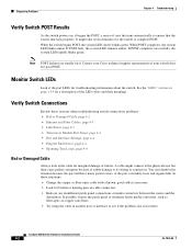
Diagnosing Problems Chapter 4 Troubleshooting Verify Switch POST Results As the switch powers on, it begins the POST, a series of subtle damage to its wiring or connectors. If POST fails, the system LED remains amber. A cable might take ...description of the LED colors and their meanings. When the switch begins POST, the system LED slowly blinks green. Note POST failures are usually fatal. Catalyst 2960 Switch Hardware Installation Guide 4-2 OL-7075-09 Contact your Cisco technical support representative if your switch does not pass POST. When POST completes, the system...
Diagnosing Problems Chapter 4 Troubleshooting Verify Switch POST Results As the switch powers on, it begins the POST, a series of subtle damage to its wiring or connectors. If POST fails, the system LED remains amber. A cable might take ...description of the LED colors and their meanings. When the switch begins POST, the system LED slowly blinks green. Note POST failures are usually fatal. Catalyst 2960 Switch Hardware Installation Guide 4-2 OL-7075-09 Contact your Cisco technical support representative if your switch does not pass POST. When POST completes, the system...
Hardware Installation Guide
Page 98
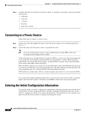
...manage the switch. This information is powered up the switch, you are usually fatal. As the switch powers on, it begins the power-on self test (POST), a series of tests that runs automatically to ensure that shipped with your switch fails POST. Call Cisco technical support... C-1. When the POST completes successfully, the System LED remains green. Catalyst 2960 Switch Hardware Installation Guide C-4 OL-7075-09 Connect the other LEDs remain solid green. POST failures are connecting the switch to a Cisco redundant power system (RPS), refer to complete the setup program, which...
...manage the switch. This information is powered up the switch, you are usually fatal. As the switch powers on, it begins the power-on self test (POST), a series of tests that runs automatically to ensure that shipped with your switch fails POST. Call Cisco technical support... C-1. When the POST completes successfully, the System LED remains green. Catalyst 2960 Switch Hardware Installation Guide C-4 OL-7075-09 Connect the other LEDs remain solid green. POST failures are connecting the switch to a Cisco redundant power system (RPS), refer to complete the setup program, which...


