Hardware Installation Guide
Page 3
... Catalyst 2960-8TC-S, Catalyst 2960-8TC-L, and Catalyst 2960G-8TC -L Switches 1-10 10/100 Ports 1-11 10/100/1000 Ports 1-11 PoE Ports (Only Catalyst 2960 PoE Switches) 1-12 SFP Module Slots 1-13 Dual-Purpose Port 1-13 Power Input Port (Catalyst 2960PD-8TT-L Switch) 1-13 LEDs 1-14 System... Port LEDs 1-18 Cable Guard for the Catalyst 2960 8-Port Switches 1-19 Rear Panel Description 1-19 Internal Power Supply 1-20 Cisco RPS 1-20 Cisco RPS 2300 1-20 Cisco RPS 675 1-21 Console Port 1-21 Security Slots 1-21 Management Options 1-22 Network Configurations 1-22 Catalyst 2960 Switch Hardware Installation...
... Catalyst 2960-8TC-S, Catalyst 2960-8TC-L, and Catalyst 2960G-8TC -L Switches 1-10 10/100 Ports 1-11 10/100/1000 Ports 1-11 PoE Ports (Only Catalyst 2960 PoE Switches) 1-12 SFP Module Slots 1-13 Dual-Purpose Port 1-13 Power Input Port (Catalyst 2960PD-8TT-L Switch) 1-13 LEDs 1-14 System... Port LEDs 1-18 Cable Guard for the Catalyst 2960 8-Port Switches 1-19 Rear Panel Description 1-19 Internal Power Supply 1-20 Cisco RPS 1-20 Cisco RPS 2300 1-20 Cisco RPS 675 1-21 Console Port 1-21 Security Slots 1-21 Management Options 1-22 Network Configurations 1-22 Catalyst 2960 Switch Hardware Installation...

Hardware Installation Guide
Page 11
.../100/1000 ports (no RPS port or SFP module slot) LAN-Lite 48 10/100BASE-TX PoE ports, 2 10/100/1000 ports, and 2 SFP module slots LAN-Lite 24 10/100BASE-TX PoE ports and 2 dual-purpose ports OL-7075-09 Catalyst 2960 Switch Hardware Installation Guide 1-1 This... switches, aggregating 10BASE-T, 100BASE-TX, and 1000BASE-T Ethernet traffic from other switches. and 48-port Catalyst 2960 switches as workstations, Cisco Wireless Access Points, Cisco IP Phones, and other network devices including servers, routers, and other network devices. Table 1-1 describes the switch model features.
.../100/1000 ports (no RPS port or SFP module slot) LAN-Lite 48 10/100BASE-TX PoE ports, 2 10/100/1000 ports, and 2 SFP module slots LAN-Lite 24 10/100BASE-TX PoE ports and 2 dual-purpose ports OL-7075-09 Catalyst 2960 Switch Hardware Installation Guide 1-1 This... switches, aggregating 10BASE-T, 100BASE-TX, and 1000BASE-T Ethernet traffic from other switches. and 48-port Catalyst 2960 switches as workstations, Cisco Wireless Access Points, Cisco IP Phones, and other network devices including servers, routers, and other network devices. Table 1-1 describes the switch model features.
Hardware Installation Guide
Page 12
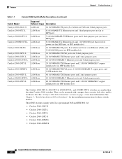
They can be mounted with Cisco prestandard PoE and IEEE 802.3af: • Catalyst 2960-24LC-S • Catalyst 2960-24LT-L •...Installation Guide 1-2 OL-7075-09 See "Catalyst 2960 8-Port Switches" section on page 1-9 for these switch models. These PoE switches comply with a magnet, have security lock slots, and do not have a fan. See Chapter 3, "Switch Installation...-48TC-L Catalyst 2960-48TT-L Supported Software Image Description LAN-Lite 24 10/100BASE-TX ports (8 of which are PoE) and 2 dual-purpose ports LAN-Base 8 10/100BASE-TX Ethernet ports and 1 dual-purpose port (no ...
They can be mounted with Cisco prestandard PoE and IEEE 802.3af: • Catalyst 2960-24LC-S • Catalyst 2960-24LT-L •...Installation Guide 1-2 OL-7075-09 See "Catalyst 2960 8-Port Switches" section on page 1-9 for these switch models. These PoE switches comply with a magnet, have security lock slots, and do not have a fan. See Chapter 3, "Switch Installation...-48TC-L Catalyst 2960-48TT-L Supported Software Image Description LAN-Lite 24 10/100BASE-TX ports (8 of which are PoE) and 2 dual-purpose ports LAN-Base 8 10/100BASE-TX Ethernet ports and 1 dual-purpose port (no ...

Hardware Installation Guide
Page 14
...-Port Switches, page 1-4 • Catalyst 2960 8-Port Switches, page 1-9 • 10/100 Ports, page 1-11 • 10/100/1000 Ports, page 1-11 • PoE Ports (Only Catalyst 2960 PoE Switches), page 1-12 • SFP Module Slots, page 1-13 • Dual-Purpose Port, page 1-13 • Power Input Port (Catalyst 2960PD-8TT-L Switch...
...-Port Switches, page 1-4 • Catalyst 2960 8-Port Switches, page 1-9 • 10/100 Ports, page 1-11 • 10/100/1000 Ports, page 1-11 • PoE Ports (Only Catalyst 2960 PoE Switches), page 1-12 • SFP Module Slots, page 1-13 • Dual-Purpose Port, page 1-13 • Power Input Port (Catalyst 2960PD-8TT-L Switch...

Hardware Installation Guide
Page 16
... (port 1) is above the second member (port 2), port 3 is above port 4, and so on the Catalyst 2960-24LC-S switch are PoE ports. Ports 1 to 8 on . Figure 1-5 SYST RPS STAT DUPLX SPEED PoE MODE Catalyst 2960-24PC-L Switch Front Panel 1 2 1X 3 4 5 6 7 8 9 10 11 12 13 14 15 16 17 ...19 20 21 22 23 24 11X 13X 23X Catalyst 2960 Series PoE-24 2X POWER OVER ETHERNET 12X 14X 1 2 24X 204641 1 2 1 10/100 PoE ports 2 Dual-purpose ports Figure 1-6 Catalyst 2960-24PC-S Switch Front Panel 206731 1 2 1 10/100 PoE ports 2 Dual-purpose ports Figure 1-7 Catalyst 2960-24LC-S Switch ...
... (port 1) is above the second member (port 2), port 3 is above port 4, and so on the Catalyst 2960-24LC-S switch are PoE ports. Ports 1 to 8 on . Figure 1-5 SYST RPS STAT DUPLX SPEED PoE MODE Catalyst 2960-24PC-L Switch Front Panel 1 2 1X 3 4 5 6 7 8 9 10 11 12 13 14 15 16 17 ...19 20 21 22 23 24 11X 13X 23X Catalyst 2960 Series PoE-24 2X POWER OVER ETHERNET 12X 14X 1 2 24X 204641 1 2 1 10/100 PoE ports 2 Dual-purpose ports Figure 1-6 Catalyst 2960-24PC-S Switch Front Panel 206731 1 2 1 10/100 PoE ports 2 Dual-purpose ports Figure 1-7 Catalyst 2960-24LC-S Switch ...
Hardware Installation Guide
Page 17
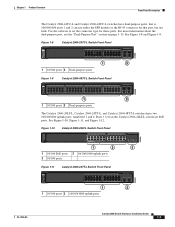
...6 7 8 9 10 11 12 13 14 15 16 17 18 19 20 21 22 23 24 Catalyst 2960 Series PoE-8 11X 13X 23X 2X POWER OVER ETHERNET 12X 14X 1 2 24X 1 2 3 1 10/100 PoE ports 3 10/100/1000 uplink ports 2 10/100 ports Figure 1-11 Catalyst 2960-24TT-L Switch Front Panel 204607 SYST... Switch Hardware Installation Guide 1-7 For more information about the dual-purpose port, see the "Dual-Purpose Port" section on the Catalyst 2960-24LT-L switch are PoE ports. Use the software to 8 on page 1-13. Figure 1-8 Catalyst 2960-24TC-L Switch Front Panel 204606 SYST RPS STAT DUPLX SPEED MODE 1 2 1 10...
...6 7 8 9 10 11 12 13 14 15 16 17 18 19 20 21 22 23 24 Catalyst 2960 Series PoE-8 11X 13X 23X 2X POWER OVER ETHERNET 12X 14X 1 2 24X 1 2 3 1 10/100 PoE ports 3 10/100/1000 uplink ports 2 10/100 ports Figure 1-11 Catalyst 2960-24TT-L Switch Front Panel 204607 SYST... Switch Hardware Installation Guide 1-7 For more information about the dual-purpose port, see the "Dual-Purpose Port" section on the Catalyst 2960-24LT-L switch are PoE ports. Use the software to 8 on page 1-13. Figure 1-8 Catalyst 2960-24TC-L Switch Front Panel 204606 SYST RPS STAT DUPLX SPEED MODE 1 2 1 10...

Hardware Installation Guide
Page 18
... Installation Guide 1-8 OL-7075-09 See Figure 1-13 and Figure 1-14. Figure 1-13 Catalyst 2960-48PST-L Switch Front Panel 3 1 2 3 4 5 6 SYST 1X RPS STAT DUPLX SPEED PoE MODE 2X POWER OVER ETHERNET 7 8 9 10 11 12 13 14 15 16 17 18 19 20 21 22 23 24 25 26 27 28 29... 2 10/100/1000 uplink ports 3 SFP module slots Figure 1-14 Catalyst 2960-48PST-S Switch Front Panel 3 206732 1 2 1 10/100 PoE ports 2 10/100/1000 uplink ports 3 SFP module slots Catalyst 2960G-24TC-L and Catalyst 2960G-48TC-L Switches The 10/100/1000 ports on the switch ...
... Installation Guide 1-8 OL-7075-09 See Figure 1-13 and Figure 1-14. Figure 1-13 Catalyst 2960-48PST-L Switch Front Panel 3 1 2 3 4 5 6 SYST 1X RPS STAT DUPLX SPEED PoE MODE 2X POWER OVER ETHERNET 7 8 9 10 11 12 13 14 15 16 17 18 19 20 21 22 23 24 25 26 27 28 29... 2 10/100/1000 uplink ports 3 SFP module slots Figure 1-14 Catalyst 2960-48PST-S Switch Front Panel 3 206732 1 2 1 10/100 PoE ports 2 10/100/1000 uplink ports 3 SFP module slots Catalyst 2960G-24TC-L and Catalyst 2960G-48TC-L Switches The 10/100/1000 ports on the switch ...

Hardware Installation Guide
Page 19
... Figure 1-17 Catalyst 2960PD-8TT-L Switch Front Panel SYST STAT DPLX SPD 1x 2x 3x 4x 5x 6x 7x 8x CONSOLE MODE Catalyst 2960 Series 1 PoE INPUT 1 2 3 1 Console port 3 10/100/1000 power input port 2 10/100 ports OL-7075-09 Catalyst 2960 Switch Hardware Installation Guide 1-9 The switch can receive...
... Figure 1-17 Catalyst 2960PD-8TT-L Switch Front Panel SYST STAT DPLX SPD 1x 2x 3x 4x 5x 6x 7x 8x CONSOLE MODE Catalyst 2960 Series 1 PoE INPUT 1 2 3 1 Console port 3 10/100/1000 power input port 2 10/100 ports OL-7075-09 Catalyst 2960 Switch Hardware Installation Guide 1-9 The switch can receive...
Hardware Installation Guide
Page 22
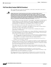
... and 2960-24PC-S, switches and ports 1 to 8 of the PoE ports on the Catalyst 2960-24LT-L and 2960-24LC-S switches provide PoE support for redundant power. The Cisco prestandard PoE is also supported for Cisco IP Phones and Cisco Aironet Access Points. • Each of the 10/100 ports on... For information about configuring and monitoring PoE ports, see the documentation that case, the PoE port becomes the backup power source for each 10/100 PoE port: - A restricted access area can connect a Cisco IP Phone or Cisco Aironet Access Point to a Catalyst 2960 PoE switch 10/100 port and to...
... and 2960-24PC-S, switches and ports 1 to 8 of the PoE ports on the Catalyst 2960-24LT-L and 2960-24LC-S switches provide PoE support for redundant power. The Cisco prestandard PoE is also supported for Cisco IP Phones and Cisco Aironet Access Points. • Each of the 10/100 ports on... For information about configuring and monitoring PoE ports, see the documentation that case, the PoE port becomes the backup power source for each 10/100 PoE port: - A restricted access area can connect a Cisco IP Phone or Cisco Aironet Access Point to a Catalyst 2960 PoE switch 10/100 port and to...
Hardware Installation Guide
Page 24
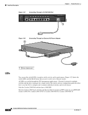
Only the Catalyst 2960 PoE switches have an RPS connector or an RPS LED: Catalyst 2960-24-S, Catalyst 2960-24TC-S, Catalyst 2960-48TT-S, Catalyst 2960-48TC-S. ...Figure 1-21 Connecting Through a 10/100/1000 Port SYST STAT DPLX SPD 1x 2x 3x 4x 5x 6x 7x 8x CONSOLE MODE Catalyst 2960 Series 1 PoE INPUT 1 204644 Figure 1-22 1 Connecting Through an External AC Power Adapter 48V , 0.3 A 270433 LEDs 1 Power adapter port You can use the...multiple switches and the device manager for a single switch. The four Catalyst 2960 8-port switches and these models do not have a PoE LED.
Only the Catalyst 2960 PoE switches have an RPS connector or an RPS LED: Catalyst 2960-24-S, Catalyst 2960-24TC-S, Catalyst 2960-48TT-S, Catalyst 2960-48TC-S. ...Figure 1-21 Connecting Through a 10/100/1000 Port SYST STAT DPLX SPD 1x 2x 3x 4x 5x 6x 7x 8x CONSOLE MODE Catalyst 2960 Series 1 PoE INPUT 1 204644 Figure 1-22 1 Connecting Through an External AC Power Adapter 48V , 0.3 A 270433 LEDs 1 Power adapter port You can use the...multiple switches and the device manager for a single switch. The four Catalyst 2960 8-port switches and these models do not have a PoE LED.

Hardware Installation Guide
Page 25
... Switch LEDs 8 Front Panel Description System LED 204612 1 2 3 4 5 6 SYST RPS STAT DUPLX SPEED PoE MODE 7 12 1X 34 56 78 9 10 11 12 11X 1 SYST LED 5 Speed LED 2 RPS LED 6 PoE LED1 3 Status LED 7 Mode button 4 Duplex LED 8 Port LEDs 1. Table 1-2 lists the LED colors and... their meanings. System is receiving power but is only on . The PoE LED is not functioning properly. The System LED shows whether the system is receiving power and is operating normally. System is functioning properly. Table 1-2 ...
... Switch LEDs 8 Front Panel Description System LED 204612 1 2 3 4 5 6 SYST RPS STAT DUPLX SPEED PoE MODE 7 12 1X 34 56 78 9 10 11 12 11X 1 SYST LED 5 Speed LED 2 RPS LED 6 PoE LED1 3 Status LED 7 Mode button 4 Duplex LED 8 Port LEDs 1. Table 1-2 lists the LED colors and... their meanings. System is receiving power but is only on . The PoE LED is not functioning properly. The System LED shows whether the system is receiving power and is operating normally. System is functioning properly. Table 1-2 ...
Hardware Installation Guide
Page 26
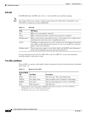
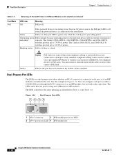
... LED. Port LEDs and Modes The port LEDs, as a group or individually, display information about the switch and about the Cisco RPS 2300 or the Cisco RPS 675, see the related hardware installation guide for Port LEDs Selected Mode LED Port Mode Description STAT Port status The port ... and 2960-48TT-S switches do not have failed. For more information about the individual ports (Table 1-4): Table 1-4 Modes for that power system. The PoE LED is in standby mode or in a fault condition. Front Panel Description Chapter 1 Product Overview RPS LED The RPS LED shows the RPS status....
... LED. Port LEDs and Modes The port LEDs, as a group or individually, display information about the switch and about the Cisco RPS 2300 or the Cisco RPS 675, see the related hardware installation guide for Port LEDs Selected Mode LED Port Mode Description STAT Port status The port ... and 2960-48TT-S switches do not have failed. For more information about the individual ports (Table 1-4): Table 1-4 Modes for that power system. The PoE LED is in standby mode or in a fault condition. Front Panel Description Chapter 1 Product Overview RPS LED The RPS LED shows the RPS status....

Hardware Installation Guide
Page 27
...fault indication. DUPLX (duplex) SPEED Off Port is sending or receiving data. Blinking green Port is operating at least one of the 10/100 PoE ports has been denied power, or at 1000 Mb/s. Table 1-6 explains how to 30 seconds as excessive collisions, cyclic redundancy check (CRC)... Port is operating in Different Modes on the port LEDs. Chapter 1 Product Overview Front Panel Description Even if the PoE mode is not selected, the PoE LED shows PoE problems when they are monitored for possible loops. Blinking green Activity. Green Port is highlighted. None of the port ...
...fault indication. DUPLX (duplex) SPEED Off Port is sending or receiving data. Blinking green Port is operating at least one of the 10/100 PoE ports has been denied power, or at 1000 Mb/s. Table 1-6 explains how to 30 seconds as excessive collisions, cyclic redundancy check (CRC)... Port is operating in Different Modes on the port LEDs. Chapter 1 Product Overview Front Panel Description Even if the PoE mode is not selected, the PoE LED shows PoE problems when they are monitored for possible loops. Blinking green Activity. Green Port is highlighted. None of the port ...
Hardware Installation Guide
Page 28
...green only when the switch port is denied because providing power to the powered device will exceed the switch power and amber capacity. Alternating green PoE is providing power. You can be used (Ethernet or SFP module). See the example in -use LED 4 SFP module slot 1-18 ... Panel Description Chapter 1 Product Overview Table 1-6 Port Mode PoE Meaning of Port LED Colors in Different Modes on the Switch (continued) LED Color Off Meaning PoE is off even if the powered device is being used to connect Cisco prestandard IP Phones or wireless access points or IEEE 802.3af...
...green only when the switch port is denied because providing power to the powered device will exceed the switch power and amber capacity. Alternating green PoE is providing power. You can be used (Ethernet or SFP module). See the example in -use LED 4 SFP module slot 1-18 ... Panel Description Chapter 1 Product Overview Table 1-6 Port Mode PoE Meaning of Port LED Colors in Different Modes on the Switch (continued) LED Color Off Meaning PoE is off even if the powered device is being used to connect Cisco prestandard IP Phones or wireless access points or IEEE 802.3af...
Hardware Installation Guide
Page 36
...of security. Do not open. Installation Guidelines This section does not apply to all Catalyst 2960 switches except for Particulate Matter Cisco Ethernet switches are made first and disconnected last. For information applicable to observe these fans and blowers can draw dust and other... mechanisms, such as metal flakes from the switch to connected devices must install this equipment in Table B-1 on Power over Ethernet (PoE) circuits if interconnections are made using such interconnection methods, unless the exposed metal parts are located within a restricted access location and...
...of security. Do not open. Installation Guidelines This section does not apply to all Catalyst 2960 switches except for Particulate Matter Cisco Ethernet switches are made first and disconnected last. For information applicable to observe these fans and blowers can draw dust and other... mechanisms, such as metal flakes from the switch to connected devices must install this equipment in Table B-1 on Power over Ethernet (PoE) circuits if interconnections are made using such interconnection methods, unless the exposed metal parts are located within a restricted access location and...

Hardware Installation Guide
Page 56
..., you must be accessible at the bottom of the rack if it can cause serious burns or weld the metal object to a power-over-ethernet (PoE) IEEE 802.3af compliant power source or an IEC60950 compliant limited power source. If the chassis falls, it is the only unit in the rack...
..., you must be accessible at the bottom of the rack if it can cause serious burns or weld the metal object to a power-over-ethernet (PoE) IEEE 802.3af compliant power source or an IEC60950 compliant limited power source. If the chassis falls, it is the only unit in the rack...
Hardware Installation Guide
Page 59
... it begins the POST, a series of tests that the switch functions properly. After a successful POST, disconnect the power cord from an upstream PoE switch. You can power the Catalyst 2960PD-8TT-L switch through a 10/100/1000 uplink port, which can blink during the test. Install the... switch in a rack, or on a desk, a shelf, or a wall, as described in the "Installing the Switch" section on Cisco.com describes the box contents. Box Contents The switch getting started guide on page 3-5. As the switch powers on the rear panel. POST lasts approximately...
... it begins the POST, a series of tests that the switch functions properly. After a successful POST, disconnect the power cord from an upstream PoE switch. You can power the Catalyst 2960PD-8TT-L switch through a 10/100/1000 uplink port, which can blink during the test. Install the... switch in a rack, or on a desk, a shelf, or a wall, as described in the "Installing the Switch" section on Cisco.com describes the box contents. Box Contents The switch getting started guide on page 3-5. As the switch powers on the rear panel. POST lasts approximately...

Hardware Installation Guide
Page 103
...adapter pinouts, terminal RJ-45-to-DB-25 B-8 RJ-45-to B-2 described 1-11 illustrated 1-4 PoE 1-12 speed indicator 1-18 10/100/1000 ports, described 1-13 10/100 ports 1-11 10/100 ports PoE 1-12 19- Numerics 10/100/1000 ports cable lengths 2-4, 3-4 connecting to 2-14 connectors and ...cables B-1 to -DB-9 B-8 attaching the Cisco RPS warning 2-2, 2-6 auto-MDIX 1-11, 2-15, 2-20, B-1, B-3, C-2 autonegotiation 1-11 ...
...adapter pinouts, terminal RJ-45-to-DB-25 B-8 RJ-45-to B-2 described 1-11 illustrated 1-4 PoE 1-12 speed indicator 1-18 10/100/1000 ports, described 1-13 10/100 ports 1-11 10/100 ports PoE 1-12 19- Numerics 10/100/1000 ports cable lengths 2-4, 3-4 connecting to 2-14 connectors and ...cables B-1 to -DB-9 B-8 attaching the Cisco RPS warning 2-2, 2-6 auto-MDIX 1-11, 2-15, 2-20, B-1, B-3, C-2 autonegotiation 1-11 ...
Hardware Installation Guide
Page 105
... internal power supply 1-20 J jewelry removal warning 2-2, 3-2 L LEDs OL-7075-09 color meanings 1-17 dual-purpose port 1-18 duplex 1-16 front panel 1-15 interpreting 1-17 PoE 1-16, 1-18 port mode 1-16, 1-17 POST results 2-6, 3-5, 4-2, C-4 RPS 1-16 speed 1-16 STATUS 1-16 system 1-15 troubleshooting with 4-1 to 4-2 lightning activity warning 2-2, 3-2 link status troubleshooting...
... internal power supply 1-20 J jewelry removal warning 2-2, 3-2 L LEDs OL-7075-09 color meanings 1-17 dual-purpose port 1-18 duplex 1-16 front panel 1-15 interpreting 1-17 PoE 1-16, 1-18 port mode 1-16, 1-17 POST results 2-6, 3-5, 4-2, C-4 RPS 1-16 speed 1-16 STATUS 1-16 system 1-15 troubleshooting with 4-1 to 4-2 lightning activity warning 2-2, 3-2 link status troubleshooting...
Hardware Installation Guide
Page 106
...to-DB-9 terminal adapter B-8 SFP module B-3 straight-through cables four twisted-pair 1000BASE-T ports B-6 two twisted-pair B-6 plug-socket combination warning 2-3 PoE LED 1-16, 1-17, 1-18 on Catalyst 2960-24PC-L, 24LT-L, and 48PST-L switches 1-12 warning 3-2 port and interface troubleshooting 4-4 port modes ...1-20 power on 2-5, 3-5 IN-4 Catalyst 2960 Switch Hardware Installation Guide power-on self test See POST Power over Ethernet See PoE Power over Ethernet See PoE power supply AC power outlet 1-20 for the Catalyst 2960PD-8TT-L switch 1-13 internal 1-20 RPS connector 1-20 power supply ...
...to-DB-9 terminal adapter B-8 SFP module B-3 straight-through cables four twisted-pair 1000BASE-T ports B-6 two twisted-pair B-6 plug-socket combination warning 2-3 PoE LED 1-16, 1-17, 1-18 on Catalyst 2960-24PC-L, 24LT-L, and 48PST-L switches 1-12 warning 3-2 port and interface troubleshooting 4-4 port modes ...1-20 power on 2-5, 3-5 IN-4 Catalyst 2960 Switch Hardware Installation Guide power-on self test See POST Power over Ethernet See PoE Power over Ethernet See PoE power supply AC power outlet 1-20 for the Catalyst 2960PD-8TT-L switch 1-13 internal 1-20 RPS connector 1-20 power supply ...
