Instruction Manual
Page 2
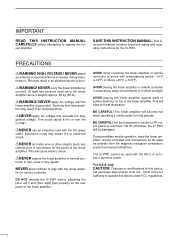
... device, not expressly approved by yourself. SAVE THIS INSTRUCTION MANUAL. NEVER carry the linear amplifier by Icom Inc., could cause a fire or ruin the IC-PW1. RNEVER use an extension cord with the AH-2 HF AUTOMATIC ANTENNA TUNER. AVOID placing the linear amplifi...°F) or above +40°C (+104°F). DO NOT operate the IC-PW1 before attempting to less than 100 W, otherwise, the IC-PW1 will become hot when operating if continuously for the IC-PW1. BE CAREFUL! The IC-PW1 cannot be damaged. AVOID using or placing the linear amplifier or ...
... device, not expressly approved by yourself. SAVE THIS INSTRUCTION MANUAL. NEVER carry the linear amplifier by Icom Inc., could cause a fire or ruin the IC-PW1. RNEVER use an extension cord with the AH-2 HF AUTOMATIC ANTENNA TUNER. AVOID placing the linear amplifi...°F) or above +40°C (+104°F). DO NOT operate the IC-PW1 before attempting to less than 100 W, otherwise, the IC-PW1 will become hot when operating if continuously for the IC-PW1. BE CAREFUL! The IC-PW1 cannot be damaged. AVOID using or placing the linear amplifier or ...
Instruction Manual
Page 5
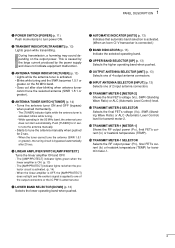
... [DOWN] (p. 13) Selects the lower operating band when pushed. u AUTOMATIC INDICATOR [AUTO] (p. 13) Indicates that automatic band selection is activated. (When an Icom CI-V transceiver is activated. (p. 14) - When the linear amplifier is OFF, the [AMP/PROTECT] does not light and the exciter's signal is ...activated; The [TUNER] indicator lights while the antenna tuner is applied to one of the output connectors or the IC-PW1's antenna tuner. The [AMP/PROTECT] indicator lights green when the linear amplifier is caused by the large current produced by ...
... [DOWN] (p. 13) Selects the lower operating band when pushed. u AUTOMATIC INDICATOR [AUTO] (p. 13) Indicates that automatic band selection is activated. (When an Icom CI-V transceiver is activated. (p. 14) - When the linear amplifier is OFF, the [AMP/PROTECT] does not light and the exciter's signal is ...activated; The [TUNER] indicator lights while the antenna tuner is applied to one of the output connectors or the IC-PW1's antenna tuner. The [AMP/PROTECT] indicator lights green when the linear amplifier is caused by the large current produced by ...
Instruction Manual
Page 6
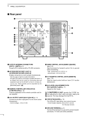
... [ALC adj1] and [ALC adj2] pots properly. w ACCESSORY SOCKET-1 [ACC-1] ACCESSORY SOCKET-2 [ACC-2] Enable connection to ground while transmitting. - Go to Icom exciters (transceivers). - This may damage the final FETs. Circuit breaker capacity: 20 A (U.S.A. Max. RCAUTION! version) 15 A (Europe version) o ... controller and linear amplifier. The [ACC-2] socket is connected in parallel with a PL-259 connector. DO NOT operate the IC-PW1 be separated by default and can be - i CIRCUIT BEAKERS (p. 14) Cut off the AC input when over current occurs. - ...
... [ALC adj1] and [ALC adj2] pots properly. w ACCESSORY SOCKET-1 [ACC-1] ACCESSORY SOCKET-2 [ACC-2] Enable connection to ground while transmitting. - Go to Icom exciters (transceivers). - This may damage the final FETs. Circuit breaker capacity: 20 A (U.S.A. Max. RCAUTION! version) 15 A (Europe version) o ... controller and linear amplifier. The [ACC-2] socket is connected in parallel with a PL-259 connector. DO NOT operate the IC-PW1 be separated by default and can be - i CIRCUIT BEAKERS (p. 14) Cut off the AC input when over current occurs. - ...
Instruction Manual
Page 10
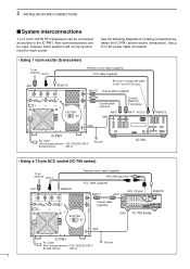
... the following diagrams for AC power cable connection. • Using 1 Icom exciter (transceiver) To an antenna ACC-1 ANT REMOTE EXCITER 1 1&2 Remote control cable (supplied) ACC cable (supplied) Be sure to connect the cable to the IC-PW1. 2 INSTALLATION AND CONNECTIONS s System interconnections 1 or 2 Icom 100 W HF transceivers can be used, however, band selection will...
... the following diagrams for AC power cable connection. • Using 1 Icom exciter (transceiver) To an antenna ACC-1 ANT REMOTE EXCITER 1 1&2 Remote control cable (supplied) ACC cable (supplied) Be sure to connect the cable to the IC-PW1. 2 INSTALLATION AND CONNECTIONS s System interconnections 1 or 2 Icom 100 W HF transceivers can be used, however, band selection will...
Instruction Manual
Page 11
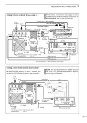
...AND CONNECTIONS • Using 2 Icom exciters (transceivers) The following connections also apply to [1&2] when 2 exciters are 5 V DC 0.1 A. To an antenna ALC1 ANT SEND1 RCA plug INPUT1 ALC SEND SEND EXCITER 1 1&2 Relay DC power GND Coaxial cable (supplied) IC-PW1 AC outlet (Non-Europe versions :... 100-120/220-240 V Europe version : 230 V) Ground RF OUT GND DC OUT SEND ALC Non-Icom exciter 8 REMOTE • Using a non-Icom exciter (transceiver) Set the [EXCITER] switch to ...
...AND CONNECTIONS • Using 2 Icom exciters (transceivers) The following connections also apply to [1&2] when 2 exciters are 5 V DC 0.1 A. To an antenna ALC1 ANT SEND1 RCA plug INPUT1 ALC SEND SEND EXCITER 1 1&2 Relay DC power GND Coaxial cable (supplied) IC-PW1 AC outlet (Non-Europe versions :... 100-120/220-240 V Europe version : 230 V) Ground RF OUT GND DC OUT SEND ALC Non-Icom exciter 8 REMOTE • Using a non-Icom exciter (transceiver) Set the [EXCITER] switch to ...
Instruction Manual
Page 12
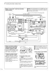
... A. ACC cable (supplied) Remote control cable (supplied) Coaxial cable (supplied) INPUT1 INPUT2 GND ACC(2) Connect ANT1 or ANT2 REMOTE IC-756 EXCITER 1 1&2 GND Non-Icom exciter ANT IC-PW1 AC outlet Coaxial cable Ground (optional) (Non-Europe versions : 100-120/220-240 V Europe version : 230 V) SEND SEND2... V DC, 0.5 A to turn the controller's LEDs OFF as shown at right. to IC-PW1 [INPUT1] 13.8 V DC [ACC-1] to IC-PW1 [GND] 6 3 1 RF GND 524 DC SEND ALC IC-PW1 (DIN) Non-Icom exciter (2) Use the auxiliary power supply Set the jumper to '2' to [INPUT2]. nected to ...
... A. ACC cable (supplied) Remote control cable (supplied) Coaxial cable (supplied) INPUT1 INPUT2 GND ACC(2) Connect ANT1 or ANT2 REMOTE IC-756 EXCITER 1 1&2 GND Non-Icom exciter ANT IC-PW1 AC outlet Coaxial cable Ground (optional) (Non-Europe versions : 100-120/220-240 V Europe version : 230 V) SEND SEND2... V DC, 0.5 A to turn the controller's LEDs OFF as shown at right. to IC-PW1 [INPUT1] 13.8 V DC [ACC-1] to IC-PW1 [GND] 6 3 1 RF GND 524 DC SEND ALC IC-PW1 (DIN) Non-Icom exciter (2) Use the auxiliary power supply Set the jumper to '2' to [INPUT2]. nected to ...
Instruction Manual
Page 15
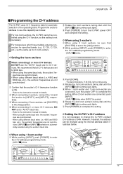
... OPERATION s Programming the CI-V address The IC-PW1 uses CI-V frequency data for specified bands (e.g. D Setting the Icom exciters When connecting 2 or more CI-V devices, DO NOT set [EXCITER] to the instruction manual for details. e When connecting 2 Icom exciters, set to the instruction manual for ...NOT use this setting is ON. - r Rotate the 1st Icom exciter's tuning dial until the [INPUT z] light continuously lights. IC-726, IC-729, etc.), set the same as follows: For non-Icom exciters, the IC-PW1 cannot be controlled using different baud rates (i.e. 4800 and 9600 ...
... OPERATION s Programming the CI-V address The IC-PW1 uses CI-V frequency data for specified bands (e.g. D Setting the Icom exciters When connecting 2 or more CI-V devices, DO NOT set [EXCITER] to the instruction manual for details. e When connecting 2 Icom exciters, set to the instruction manual for ...NOT use this setting is ON. - r Rotate the 1st Icom exciter's tuning dial until the [INPUT z] light continuously lights. IC-726, IC-729, etc.), set the same as follows: For non-Icom exciters, the IC-PW1 cannot be controlled using different baud rates (i.e. 4800 and 9600 ...
Instruction Manual
Page 16
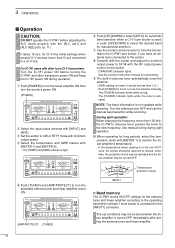
...;er is in antenna tuner automatically tunes the antenna. - 3 OPERATION s Operation CAUTION: DO NOT operate the IC-PW1 before turning the IC-PW1 and other Icom CI-V transceivers: Turn the IC-781 power ON before adjusting the ALC levels properly with [METER-1] and [METER-2]. - for CI-V line initial... tuning during operation. Temperature protection range METER-1 D Band memory The IC-PW1 stores ON/OFF settings for the antenna tuner and linear amplifier according to the operating band when at least 1 Icom exciter is connected to select the desired band for automatic band selection ...
...;er is in antenna tuner automatically tunes the antenna. - 3 OPERATION s Operation CAUTION: DO NOT operate the IC-PW1 before turning the IC-PW1 and other Icom CI-V transceivers: Turn the IC-781 power ON before adjusting the ALC levels properly with [METER-1] and [METER-2]. - for CI-V line initial... tuning during operation. Temperature protection range METER-1 D Band memory The IC-PW1 stores ON/OFF settings for the antenna tuner and linear amplifier according to the operating band when at least 1 Icom exciter is connected to select the desired band for automatic band selection ...
Instruction Manual
Page 19
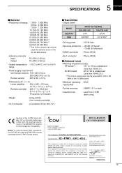
...included) • Weight : 25 kg (55 lb) (incl. Icom Inc. Japan 6-9-16, Kamihigashi, Hirano-ku Osaka 547-0002, Japan DECLARATION OF CONFORMITY Kind of equipment: HF+50 MHz 1 KW LINEAR AMPLIFIER Type-designation: IC-PW1 + opC-853 These equipments comply with the requirements of the 73/... ETS300 684 (EMC product standard for Electromagnetic Compatibility. NOTE: To meet European EMC regulations, the OPC-853 AC cable with the essential requirements of the IC-PW1 which display "CE" on the 24-28 MHz bands. • Antenna connector : Input PL-239 × 2 (50 Ω) Output PL-239 ...
...included) • Weight : 25 kg (55 lb) (incl. Icom Inc. Japan 6-9-16, Kamihigashi, Hirano-ku Osaka 547-0002, Japan DECLARATION OF CONFORMITY Kind of equipment: HF+50 MHz 1 KW LINEAR AMPLIFIER Type-designation: IC-PW1 + opC-853 These equipments comply with the requirements of the 73/... ETS300 684 (EMC product standard for Electromagnetic Compatibility. NOTE: To meet European EMC regulations, the OPC-853 AC cable with the essential requirements of the IC-PW1 which display "CE" on the 24-28 MHz bands. • Antenna connector : Input PL-239 × 2 (50 Ω) Output PL-239 ...


