Instruction Manual
Page 2
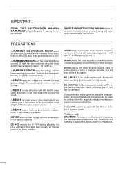
...: Changes or modifications to play with the AH-2 HF AUTOMATIC ANTENNA TUNER. NEVER carry the linear amplifier by Icom Inc., could cause a fire or ruin the IC-PW1. RNEVER use an extension cord with temperatures below -10°C (+14°F) or above +40°C (+104°F). The linear amplifier...
...: Changes or modifications to play with the AH-2 HF AUTOMATIC ANTENNA TUNER. NEVER carry the linear amplifier by Icom Inc., could cause a fire or ruin the IC-PW1. RNEVER use an extension cord with temperatures below -10°C (+14°F) or above +40°C (+104°F). The linear amplifier...
Instruction Manual
Page 5
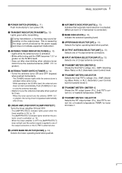
...or heatsink temperature (TEMP) for transmit meter-1. 2 u AUTOMATIC INDICATOR [AUTO] (p. 13) Indicates that automatic band selection is activated. (When an Icom CI-V transceiver is ON. (p. 13) - The [AMP/PROTECT] indicator lights green when the linear amplifier is connected.) i BAND ...TUNER] for 2 sec. - 1 PANEL DESCRIPTION q POWER SWITCH [POWER] (p. 11) Push momentarily to one of the output connectors or the IC-PW1's antenna tuner. w TRANSMIT INDICATOR [TRANSMIT] (p. 13) Lights green while transmitting. During transmission, a humming may sound depending on the 50 MHz ...
...or heatsink temperature (TEMP) for transmit meter-1. 2 u AUTOMATIC INDICATOR [AUTO] (p. 13) Indicates that automatic band selection is activated. (When an Icom CI-V transceiver is ON. (p. 13) - The [AMP/PROTECT] indicator lights green when the linear amplifier is connected.) i BAND ...TUNER] for 2 sec. - 1 PANEL DESCRIPTION q POWER SWITCH [POWER] (p. 11) Push momentarily to one of the output connectors or the IC-PW1's antenna tuner. w TRANSMIT INDICATOR [TRANSMIT] (p. 13) Lights green while transmitting. During transmission, a humming may sound depending on the 50 MHz ...
Instruction Manual
Page 6
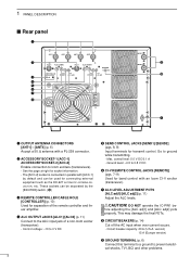
...0 V DC t SEND CONTROL JACKS [SEND1]/[SEND2] (pgs. 8, 9) Input terminals for transmit control. Max. DO NOT operate the IC-PW1 be used for connecting external equipment such as the EX-627 AUTOMATIC ANTENNA SELECTOR, etc. u ALC LEVEL ADJUSTMENT POTS [ALC adj1]/[ALC... SOCKET-1 [ACC-1] ACCESSORY SOCKET-2 [ACC-2] Enable connection to 0.8 V DC y CI-V REMOTE CONTROL JACKS [REMOTE] (pgs. 7-9) Used for band control with an Icom CI-V exciter (transceiver). Circuit breaker capacity: 20 A (U.S.A. See the page at right for socket information. - 1 PANEL DESCRIPTION s Rear panel q w e r ...
...0 V DC t SEND CONTROL JACKS [SEND1]/[SEND2] (pgs. 8, 9) Input terminals for transmit control. Max. DO NOT operate the IC-PW1 be used for connecting external equipment such as the EX-627 AUTOMATIC ANTENNA SELECTOR, etc. u ALC LEVEL ADJUSTMENT POTS [ALC adj1]/[ALC... SOCKET-1 [ACC-1] ACCESSORY SOCKET-2 [ACC-2] Enable connection to 0.8 V DC y CI-V REMOTE CONTROL JACKS [REMOTE] (pgs. 7-9) Used for band control with an Icom CI-V exciter (transceiver). Circuit breaker capacity: 20 A (U.S.A. See the page at right for socket information. - 1 PANEL DESCRIPTION s Rear panel q w e r ...
Instruction Manual
Page 10
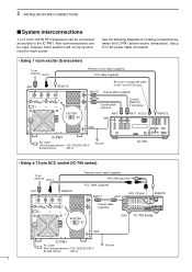
...) To an antenna ACC-1 ANT REMOTE EXCITER 1 1&2 Remote control cable (supplied) ACC cable (supplied) Be sure to connect the cable to the IC-PW1. 2 INSTALLATION AND CONNECTIONS s System interconnections 1 or 2 Icom 100 W HF transceivers can be used, however, band selection will not be connected as exciters to the 7-pin ACC(2) jack. See the...
...) To an antenna ACC-1 ANT REMOTE EXCITER 1 1&2 Remote control cable (supplied) ACC cable (supplied) Be sure to connect the cable to the IC-PW1. 2 INSTALLATION AND CONNECTIONS s System interconnections 1 or 2 Icom 100 W HF transceivers can be used, however, band selection will not be connected as exciters to the 7-pin ACC(2) jack. See the...
Instruction Manual
Page 11
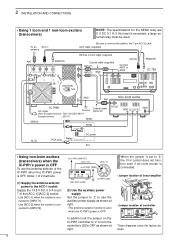
... SEND1 RCA plug INPUT1 ALC SEND SEND EXCITER 1 1&2 Relay DC power GND Coaxial cable (supplied) IC-PW1 AC outlet (Non-Europe versions : 100-120/220-240 V Europe version : 230 V) Ground RF OUT GND DC OUT SEND ALC Non-Icom exciter 8 NOTE: The specifications for specified bands (e.g. 2 INSTALLATION AND CONNECTIONS...
... SEND1 RCA plug INPUT1 ALC SEND SEND EXCITER 1 1&2 Relay DC power GND Coaxial cable (supplied) IC-PW1 AC outlet (Non-Europe versions : 100-120/220-240 V Europe version : 230 V) Ground RF OUT GND DC OUT SEND ALC Non-Icom exciter 8 NOTE: The specifications for specified bands (e.g. 2 INSTALLATION AND CONNECTIONS...
Instruction Manual
Page 12
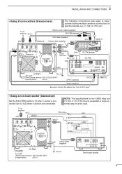
...ACC cable (supplied) Remote control cable (supplied) Coaxial cable (supplied) INPUT1 INPUT2 GND ACC(2) Connect ANT1 or ANT2 REMOTE IC-756 EXCITER 1 1&2 GND Non-Icom exciter ANT IC-PW1 AC outlet Coaxial cable Ground (optional) (Non-Europe versions : 100-120/220-240 V Europe version : 230 V) SEND... an ACC-1 antenna ANT REMOTE Be sure to connect the cable to [INPUT1]. - to IC-PW1 [INPUT1] 13.8 V DC [ACC-1] to IC-PW1 [GND] 6 3 1 RF GND 524 DC SEND ALC IC-PW1 (DIN) Non-Icom exciter (2) Use the auxiliary power supply Set the jumper to '2' to [INPUT2]. When the...
...ACC cable (supplied) Remote control cable (supplied) Coaxial cable (supplied) INPUT1 INPUT2 GND ACC(2) Connect ANT1 or ANT2 REMOTE IC-756 EXCITER 1 1&2 GND Non-Icom exciter ANT IC-PW1 AC outlet Coaxial cable Ground (optional) (Non-Europe versions : 100-120/220-240 V Europe version : 230 V) SEND... an ACC-1 antenna ANT REMOTE Be sure to connect the cable to [INPUT1]. - to IC-PW1 [INPUT1] 13.8 V DC [ACC-1] to IC-PW1 [GND] 6 3 1 RF GND 524 DC SEND ALC IC-PW1 (DIN) Non-Icom exciter (2) Use the auxiliary power supply Set the jumper to '2' to [INPUT2]. When the...
Instruction Manual
Page 15
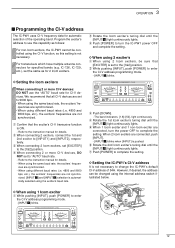
...internal address switch illustrated below. Refer to [INPUT1] and [INPUT2], respectively. e When connecting 2 Icom exciters, set the same as follows: For non-Icom exciters, the IC-PW1 cannot be changed using the CI-V function, so this setting is set to the [1&2] position. ... push [POWER] to the instruction manual for details. - D Setting the IC-PW1's CI-V address It is pushed. 3 OPERATION s Programming the CI-V address The IC-PW1 uses CI-V frequency data for automatic selection of 54H. When 2 Icom exciters are not synchronized. [INPUT z] and [INPUT x] selection is ON...
...internal address switch illustrated below. Refer to [INPUT1] and [INPUT2], respectively. e When connecting 2 Icom exciters, set the same as follows: For non-Icom exciters, the IC-PW1 cannot be changed using the CI-V function, so this setting is set to the [1&2] position. ... push [POWER] to the instruction manual for details. - D Setting the IC-PW1's CI-V address It is pushed. 3 OPERATION s Programming the CI-V address The IC-PW1 uses CI-V frequency data for automatic selection of 54H. When 2 Icom exciters are not synchronized. [INPUT z] and [INPUT x] selection is ON...
Instruction Manual
Page 16
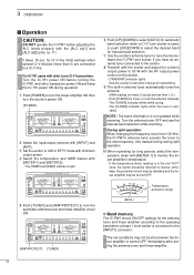
...manual band selection. Temperature protection range METER-1 D Band memory The IC-PW1 stores ON/OFF settings for the antenna tuner and linear amplifier according to the operating band when at least 1 Icom exciter is turned OFF immediately after setting the antenna tuner and ...s Operation CAUTION: DO NOT operate the IC-PW1 before turning the IC-PW1 and other transceiver power ON and keep the IC-781 power ON during split operation. !0 When operating for long periods, select the temperature meter with other Icom CI-V transceivers: Turn the IC-781 power ON before adjusting the ALC ...
...manual band selection. Temperature protection range METER-1 D Band memory The IC-PW1 stores ON/OFF settings for the antenna tuner and linear amplifier according to the operating band when at least 1 Icom exciter is turned OFF immediately after setting the antenna tuner and ...s Operation CAUTION: DO NOT operate the IC-PW1 before turning the IC-PW1 and other transceiver power ON and keep the IC-781 power ON during split operation. !0 When operating for long periods, select the temperature meter with other Icom CI-V transceivers: Turn the IC-781 power ON before adjusting the ALC ...
Instruction Manual
Page 19
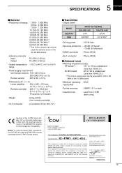
...the requirements of equipment: HF+50 MHz 1 KW LINEAR AMPLIFIER Type-designation: IC-PW1 + opC-853 These equipments comply with EMC filter must be tuned within 1.80-1.95 MHz of the IC-PW1 which display "CE" on the 24-28 MHz bands. • Antenna... unbalanced (Less than VSWR 3:1) 50 MHz band 20 to the IC-PW1 Europe version. These equipments also comply with the essential requirements of issue Icom (Europe) GmbH Himmelgeister straße 100 D-40225 Düsseldorf Authorized representative name Icom (Europe) GmbH T. 5 SPECIFICATIONS s General • Frequency coverage...
...the requirements of equipment: HF+50 MHz 1 KW LINEAR AMPLIFIER Type-designation: IC-PW1 + opC-853 These equipments comply with EMC filter must be tuned within 1.80-1.95 MHz of the IC-PW1 which display "CE" on the 24-28 MHz bands. • Antenna... unbalanced (Less than VSWR 3:1) 50 MHz band 20 to the IC-PW1 Europe version. These equipments also comply with the essential requirements of issue Icom (Europe) GmbH Himmelgeister straße 100 D-40225 Düsseldorf Authorized representative name Icom (Europe) GmbH T. 5 SPECIFICATIONS s General • Frequency coverage...


