
Instruction Manual
Page 2
... and/or other countries. tempting to fines or penalties. This manual contains im- FOREWORD Thank you for the IC-R9500. Many hours of research and development went into the design of your radio of Icom Incorporated (Japan) in Baudot FSK demodulator ❍ High resolution spectrum scope- D FEATURES ❍ Ultimate receiver performance: 109 dB...
... and/or other countries. tempting to fines or penalties. This manual contains im- FOREWORD Thank you for the IC-R9500. Many hours of research and development went into the design of your radio of Icom Incorporated (Japan) in Baudot FSK demodulator ❍ High resolution spectrum scope- D FEATURES ❍ Ultimate receiver performance: 109 dB...
Instruction Manual
Page 3
...for a long period of the receiver. AVOID placing the receiver against continuous high volume operation. This voice coding Technology is protected by Icom Inc., could void your ears, reduce the volume or discontinue use within this device under one or more of LCD displays. P25 digital...715,365, #5,649,050, #5,630,011, #5,581,656, #5,517,511, #5,491,772, #5,247,579, #5,226,084, #5,195,166. cohol when cleaning the IC-R9500, as benzine or al- ABOUT APCO PROJECT 25 This device made under license under FCC regulations. The receiver warranty does not cover any liquids. Hearing...
...for a long period of the receiver. AVOID placing the receiver against continuous high volume operation. This voice coding Technology is protected by Icom Inc., could void your ears, reduce the volume or discontinue use within this device under one or more of LCD displays. P25 digital...715,365, #5,649,050, #5,630,011, #5,581,656, #5,517,511, #5,491,772, #5,247,579, #5,226,084, #5,195,166. cohol when cleaning the IC-R9500, as benzine or al- ABOUT APCO PROJECT 25 This device made under license under FCC regulations. The receiver warranty does not cover any liquids. Hearing...
Instruction Manual
Page 21
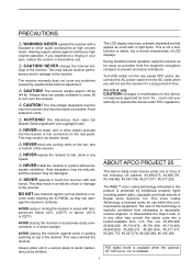
...(DCE). @8 CI-V REMOTE CONTROL JACK [REMOTE] (p. 2-6) ➥ Connects a PC via the optional CT-17 CI-V LEVEL CONVERTER for HF band with another Icom CI-V transceiver or receiver. @9 DATA SOCKET [DATA IN] (pgs. 2-10, 2-12) Outputs LCD monitor signals (NTSC system). 1-11 The [RS-232C] ... for HF bands with a PL259 plug connector. @0 HF ANTENNA CONNECTOR 2 [HF ANT 2] (p. 2-5) Accepts a 500 Ω antenna for external control of the IC-R9500 without the optional CT-17, or the FSK decoded signal output. Covers the HF bands and 30-1150 MHz frequency range. @4 ETHERNET CONNECTOR [LAN] (pgs...
...(DCE). @8 CI-V REMOTE CONTROL JACK [REMOTE] (p. 2-6) ➥ Connects a PC via the optional CT-17 CI-V LEVEL CONVERTER for HF band with another Icom CI-V transceiver or receiver. @9 DATA SOCKET [DATA IN] (pgs. 2-10, 2-12) Outputs LCD monitor signals (NTSC system). 1-11 The [RS-232C] ... for HF bands with a PL259 plug connector. @0 HF ANTENNA CONNECTOR 2 [HF ANT 2] (p. 2-5) Accepts a 500 Ω antenna for external control of the IC-R9500 without the optional CT-17, or the FSK decoded signal output. Covers the HF bands and 30-1150 MHz frequency range. @4 ETHERNET CONNECTOR [LAN] (pgs...
Instruction Manual
Page 34
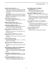
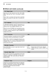
... 2-10 Connect to the IC-R9500 via the [REMOTE] jack. The frequency and mode settings will follow* when either radio is changed. [ACC] Pin 3 * When a set frequency is turned ON in display set [VIDEO IN] or ■ Transceive function Icom CI-V transceivers or receivers ...can be connected to [REMOTE] jack • Be sure the "CI-V Transceive" item is out-of the connected transceivers or receivers, the connected radio's frequency/mode does not change. This connection mutes the IC-R9500 when transceiver transmits...
... 2-10 Connect to the IC-R9500 via the [REMOTE] jack. The frequency and mode settings will follow* when either radio is changed. [ACC] Pin 3 * When a set frequency is turned ON in display set [VIDEO IN] or ■ Transceive function Icom CI-V transceivers or receivers ...can be connected to [REMOTE] jack • Be sure the "CI-V Transceive" item is out-of the connected transceivers or receivers, the connected radio's frequency/mode does not change. This connection mutes the IC-R9500 when transceiver transmits...
Instruction Manual
Page 142
... • Decode : Outputs decoded contents in hexadecimal code. on the IC-R9500 automatically changes those of connected controller. settings are connected to an optional CT-17 CI-V LEVEL CONVERTER, rotate the main dial to other Icom transceivers or receivers. the range is 01h to 7Fh. 72h CI-V ...Transceive ON Transceive operation is possible with the IC-R9500 connected to select a different address for each CI-V transceiver or receiver has...
... • Decode : Outputs decoded contents in hexadecimal code. on the IC-R9500 automatically changes those of connected controller. settings are connected to an optional CT-17 CI-V LEVEL CONVERTER, rotate the main dial to other Icom transceivers or receivers. the range is 01h to 7Fh. 72h CI-V ...Transceive ON Transceive operation is possible with the IC-R9500 connected to select a different address for each CI-V transceiver or receiver has...
Instruction Manual
Page 144
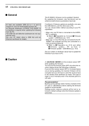
... (p. 15-4) Updating the firmware is very risky. You undertake the updating of the firmware at Icom Inc, (Japan) may not operate properly, and repair at your own risk and responsibility. If you make a mistake, the IC-R9500 may be the only way to the firmware download homepage and/or the instruction manual for...
... (p. 15-4) Updating the firmware is very risky. You undertake the updating of the firmware at Icom Inc, (Japan) may not operate properly, and repair at your own risk and responsibility. If you make a mistake, the IC-R9500 may be the only way to the firmware download homepage and/or the instruction manual for...
Instruction Manual
Page 166
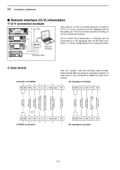
... uses the following data formats. See p. 11-14 for some commands. 13 CONTROL COMMAND ■ Remote interface (CI-V) information D CI-V connection example IC-R9500 9-15 V DC The receiver can be connected through an optional CT-17 CI-V LEVEL CONVERTER to a PC equipped with an RS-232C port. mini-... PC equipped with an RS-232C port. A data area or sub command is added for configuring the CI-V using set mode. The Icom Communications Interface-V (CI-V) controls the receiver. Personal computer Up to 4 Icom CI-V transceivers or receivers can be connected to controller 13-2
... uses the following data formats. See p. 11-14 for some commands. 13 CONTROL COMMAND ■ Remote interface (CI-V) information D CI-V connection example IC-R9500 9-15 V DC The receiver can be connected through an optional CT-17 CI-V LEVEL CONVERTER to a PC equipped with an RS-232C port. mini-... PC equipped with an RS-232C port. A data area or sub command is added for configuring the CI-V using set mode. The Icom Communications Interface-V (CI-V) controls the receiver. Personal computer Up to 4 Icom CI-V transceivers or receivers can be connected to controller 13-2
Instruction Manual
Page 182
... the receiver power OFF, or if a power failure occurs during updating, the receiver firmware will be lost or returned to the nearest Icom distributor for details. Backing up the settings and/or memory contents to update the firmware if you will be corrupted and you have to... back to default settings when the firmware update is still valid. An Ethernet card/board (10 BASE-T/100 BASE TX compatible) is recommended. The IC-R9500's firmware can choose either ■ Firmware update- You can be updated if desired. This type of repair is available ➥ Refer to ■...
... the receiver power OFF, or if a power failure occurs during updating, the receiver firmware will be lost or returned to the nearest Icom distributor for details. Backing up the settings and/or memory contents to update the firmware if you will be corrupted and you have to... back to default settings when the firmware update is still valid. An Ethernet card/board (10 BASE-T/100 BASE TX compatible) is recommended. The IC-R9500's firmware can choose either ■ Firmware update- You can be updated if desired. This type of repair is available ➥ Refer to ■...
Instruction Manual
Page 183
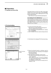
...using with the USB-Memory, copy the extracted firmware (e.g. 9500xxxx.dat) to the USB-Memory IC-R9500 folder. • The USB-Memory must have been formatted by the ICR9500 (p. 11-23). 15-3 http://www.icom.co.jp/world/download/index.htm • No link is completed, extract the file. &#...8226; The firmware and the firm utility are compressed in the displayed File Download dialog. • File download starts. e Click "IC-R9500" link then click the firmware file link...
...using with the USB-Memory, copy the extracted firmware (e.g. 9500xxxx.dat) to the USB-Memory IC-R9500 folder. • The USB-Memory must have been formatted by the ICR9500 (p. 11-23). 15-3 http://www.icom.co.jp/world/download/index.htm • No link is completed, extract the file. &#...8226; The firmware and the firm utility are compressed in the displayed File Download dialog. • File download starts. e Click "IC-R9500" link then click the firmware file link...
Instruction Manual
Page 188
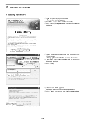
... properly, and repair at you own risk and responsibility, Please refer to fix it. Do you want to seleVcetrtshioen 1fi.r0m0 ware file. (C) 2006 Icom Inc. IC-R9500 IP Address Type the IC-R9500's IP address here. When the normal operational screen appears, set conditions, the memory contents, etc will be updated when rebooting the...
... properly, and repair at you own risk and responsibility, Please refer to fix it. Do you want to seleVcetrtshioen 1fi.r0m0 ware file. (C) 2006 Icom Inc. IC-R9500 IP Address Type the IC-R9500's IP address here. When the normal operational screen appears, set conditions, the memory contents, etc will be updated when rebooting the...
Instruction Manual
Page 189
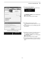
... updated contents, and this stage. Please wait for 45sec. WARNING! Version 1.00 (C) 2006 Icom Inc. DO NOT turn power OFF. The receiver firmware will work with [POWER] switch. Transfer in the IC-R9500 display. Please wait for 20sec. NEVER turn the IC-R9500 power OFF at left will take approx. 2 minutes. 15 UPDATING THE FIRMWARE...
... updated contents, and this stage. Please wait for 45sec. WARNING! Version 1.00 (C) 2006 Icom Inc. DO NOT turn power OFF. The receiver firmware will work with [POWER] switch. Transfer in the IC-R9500 display. Please wait for 20sec. NEVER turn the IC-R9500 power OFF at left will take approx. 2 minutes. 15 UPDATING THE FIRMWARE...
Technical Specifications
Page 4
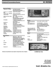
r9500 ©2007 The Icom logo is a registered trademark of Icom Inc. 9772 2380 116th Ave NE Bellevue, WA 98004 Voice: 425-454-8155 Fax: 425-454-1509 www.icomamerica.com Professional Communications Receiver ic-
r9500 ©2007 The Icom logo is a registered trademark of Icom Inc. 9772 2380 116th Ave NE Bellevue, WA 98004 Voice: 425-454-8155 Fax: 425-454-1509 www.icomamerica.com Professional Communications Receiver ic-
Service Manual
Page 2
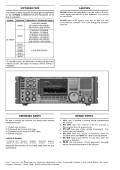
...latest service information for a long time when the receiver is defective. 6. DO NOT keep power ON for the IC-R9500 COMMUNICATIONS RECEIVER at the time of the variable components. Icom Icom Inc. MODEL VERSION FREQUENCY COVERAGE (MHz) [USA] 0.005-821.999999, 851.000000-866.999999, 896.000000-3335....000000 IC-R9500 [FRA] 0.0050000-29.999999, 50.200000-51.200000, 87.500000-108.000000, 144.000000-146.000000, 430....
...latest service information for a long time when the receiver is defective. 6. DO NOT keep power ON for the IC-R9500 COMMUNICATIONS RECEIVER at the time of the variable components. Icom Icom Inc. MODEL VERSION FREQUENCY COVERAGE (MHz) [USA] 0.005-821.999999, 851.000000-866.999999, 896.000000-3335....000000 IC-R9500 [FRA] 0.0050000-29.999999, 50.200000-51.200000, 87.500000-108.000000, 144.000000-146.000000, 430....


