
Instruction Manual
Page 1
COMMUNICATIONS RECEIVER iR9500 Instruction Manual A-6553H-1EX-q Printed in Japan © 2007 Icom Inc.
COMMUNICATIONS RECEIVER iR9500 Instruction Manual A-6553H-1EX-q Printed in Japan © 2007 Icom Inc.
Instruction Manual
Page 3
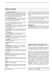
... receiver with temperatures below ±0°C (+32°F) or above +50°C (+122°F). cohol when cleaning the IC-R9500, as benzine or al- For U.S.A. ABOUT APCO PROJECT 25 This device made under license under FCC regulations. Always place unit in your authority to prevent erroneous indications. R NEVER block any problems caused by Icom...
... receiver with temperatures below ±0°C (+32°F) or above +50°C (+122°F). cohol when cleaning the IC-R9500, as benzine or al- For U.S.A. ABOUT APCO PROJECT 25 This device made under license under FCC regulations. Always place unit in your authority to prevent erroneous indications. R NEVER block any problems caused by Icom...
Instruction Manual
Page 20
... a tape recorder. y SPEECH OUTPUT JACK [SPEECH OUT] (p. 2-9) Outputs an operating frequency, mode, S-meter indication and time with WFM mode are received. o DETECTOR OUTPUT JACK [DET OUT] Outputs the detector output signal. !0 VIDEO INPUT JACK [VIDEO IN] Accepts video signals for a tape recorder AUX...V DC input. i RECORDER REMOTE JACK [REC REMOTE] Controls the operation of external equipment such as an automatic antenna selector, a TNC for data communications, etc. • See p. 2-12 for recording. Output level is the same level as a vehicle's battery. 1-10 This socket does not ...
... a tape recorder. y SPEECH OUTPUT JACK [SPEECH OUT] (p. 2-9) Outputs an operating frequency, mode, S-meter indication and time with WFM mode are received. o DETECTOR OUTPUT JACK [DET OUT] Outputs the detector output signal. !0 VIDEO INPUT JACK [VIDEO IN] Accepts video signals for a tape recorder AUX...V DC input. i RECORDER REMOTE JACK [REC REMOTE] Controls the operation of external equipment such as an automatic antenna selector, a TNC for data communications, etc. • See p. 2-12 for recording. Output level is the same level as a vehicle's battery. 1-10 This socket does not ...
Instruction Manual
Page 35
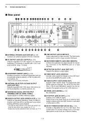
... SQELCH IN GND AUDIO INPUT Connect to the terminal unit's instructions. The narrow filter settings may not pass FSK signals. e Set the receiver to the desired frequency as below . RS-232C TNC or scan converter Personal computer 2-11 FM mode: [Setting frequency (displayed freq.)]... of Mark and Space freq.] CW narrow mode: [Setting frequency (displayed freq.)] = [Desired freq.] - [Center of the application for HF band data communications). q Connect a terminal unit as shown to the right. Be sure to select the appropriate IF filters corresponding to the signal width. (p. 5-12) &#...
... SQELCH IN GND AUDIO INPUT Connect to the terminal unit's instructions. The narrow filter settings may not pass FSK signals. e Set the receiver to the desired frequency as below . RS-232C TNC or scan converter Personal computer 2-11 FM mode: [Setting frequency (displayed freq.)]... of Mark and Space freq.] CW narrow mode: [Setting frequency (displayed freq.)] = [Desired freq.] - [Center of the application for HF band data communications). q Connect a terminal unit as shown to the right. Be sure to select the appropriate IF filters corresponding to the signal width. (p. 5-12) &#...
Instruction Manual
Page 49
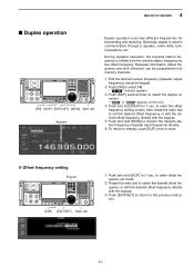
...select FM. • " F M " indicator appears. During repeater operation, the transmit station frequency is used in communication through a repeater, some utility communications, etc. to the previous indication. 4-3 4 RECEIVE MODES ■ Duplex operation [FM] [DUP] [EXIT/SET] [MONI] Main dial Appears Duplex operation uses two different...input frequency) directly. D Offset frequency setting Keypad [DUP] [EXIT/SET] Main dial q Push and hold [DUP] for transmitting and receiving. t Push and hold [MONI] to select the duplex direction. • " DUP- e Push [EXIT/SET] to return to...
...select FM. • " F M " indicator appears. During repeater operation, the transmit station frequency is used in communication through a repeater, some utility communications, etc. to the previous indication. 4-3 4 RECEIVE MODES ■ Duplex operation [FM] [DUP] [EXIT/SET] [MONI] Main dial Appears Duplex operation uses two different...input frequency) directly. D Offset frequency setting Keypad [DUP] [EXIT/SET] Main dial q Push and hold [DUP] for transmitting and receiving. t Push and hold [MONI] to select the duplex direction. • " DUP- e Push [EXIT/SET] to return to...
Instruction Manual
Page 166
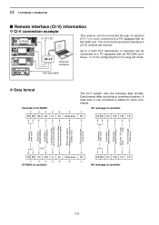
...Controller to command numbers. Data formats differ according to IC-R9500 q w ert FE FE 72H E0 Cn Sc y Data area The CI-V system uses the following data formats. Personal computer Up to 4 Icom CI-V transceivers or receivers can be connected to a PC equipped with an ...code data for some commands. The Icom Communications Interface-V (CI-V) controls the receiver. See p. 11-14 for configuring the CI-V using set mode. 13 CONTROL COMMAND ■ Remote interface (CI-V) information D CI-V connection example IC-R9500 9-15 V DC The receiver can be connected through an optional CT...
...Controller to command numbers. Data formats differ according to IC-R9500 q w ert FE FE 72H E0 Cn Sc y Data area The CI-V system uses the following data formats. Personal computer Up to 4 Icom CI-V transceivers or receivers can be connected to a PC equipped with an ...code data for some commands. The Icom Communications Interface-V (CI-V) controls the receiver. See p. 11-14 for configuring the CI-V using set mode. 13 CONTROL COMMAND ■ Remote interface (CI-V) information D CI-V connection example IC-R9500 9-15 V DC The receiver can be connected through an optional CT...
Instruction Manual
Page 188
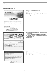
... updating of the above? Do you make a mistake, the IC-R9500 may not operate properly, and repair at Icom Inc.(Japan) may be lost when making a firmware update. Click to continue IC-R9500 Firm Utility iR9500 COMMUNICATIONS RECEIVER Firmware File Name Click [...] to fix it. y Click ... [Start] button. Firm Utility ===CAUTION=== Updating the firmware is recommended. Turn the IC-R9500 power ON. 15 UPDATING THE FIRMWARE D Updating from the PC iR9500 COMMUNICATIONS RECEIVER q Start up the IC-R9500 Firm Utility. • The window as the location. It will take approx. 2...
... updating of the above? Do you make a mistake, the IC-R9500 may not operate properly, and repair at Icom Inc.(Japan) may be lost when making a firmware update. Click to continue IC-R9500 Firm Utility iR9500 COMMUNICATIONS RECEIVER Firmware File Name Click [...] to fix it. y Click ... [Start] button. Firm Utility ===CAUTION=== Updating the firmware is recommended. Turn the IC-R9500 power ON. 15 UPDATING THE FIRMWARE D Updating from the PC iR9500 COMMUNICATIONS RECEIVER q Start up the IC-R9500 Firm Utility. • The window as the location. It will take approx. 2...
Instruction Manual
Page 189
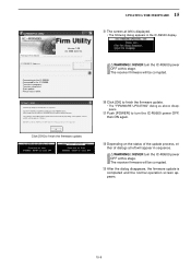
...IC-R9500 Firm Utility iR9500 COMMUNICATIONS RECEIVER Firmware File Name IC-R9500 IP Address Connecting to finish the firmware update. Firmware up dating for the main CPU is displayed. • The following dialog appears in the IC-R9500 display. Turn the IC-R9500 power OFF, then ON again with the updated firmware. Click [OK] to the IC-R9500...wait a while. Version 1.00 (C) 2006 Icom Inc. o The screen at left is completed. Transfer successful. DO NOT turn the IC-R9500 power OFF at this stage. Please wait for 45sec. The receiver firmware will be corrupted. !3 After the ...
...IC-R9500 Firm Utility iR9500 COMMUNICATIONS RECEIVER Firmware File Name IC-R9500 IP Address Connecting to finish the firmware update. Firmware up dating for the main CPU is displayed. • The following dialog appears in the IC-R9500 display. Turn the IC-R9500 power OFF, then ON again with the updated firmware. Click [OK] to the IC-R9500...wait a while. Version 1.00 (C) 2006 Icom Inc. o The screen at left is completed. Transfer successful. DO NOT turn the IC-R9500 power OFF at this stage. Please wait for 45sec. The receiver firmware will be corrupted. !3 After the ...
Instruction Manual
Page 190
...32, Kamiminami, Hirano-ku Osaka 547-0003, Japan Declare on conformity with the essential requirements of issue Icom (Europe) GmbH Himmelgeister straße 100 D-40225 Düsseldorf Authorized representative name H. Kind of equipment: COMMUNICATIONS RECEIVER Type-designation: iR9500 Version (where applicable): This compliance is based on our sole responsibility that this ... Terminal Equipment Directive, 1999/5/EC, and that any applicable Essential Test Suite measurements have been performed. ABOUT CE DECLARATION OF CONFORMITY We Icom Inc. Ikegami General Manager Signature iv)v)
...32, Kamiminami, Hirano-ku Osaka 547-0003, Japan Declare on conformity with the essential requirements of issue Icom (Europe) GmbH Himmelgeister straße 100 D-40225 Düsseldorf Authorized representative name H. Kind of equipment: COMMUNICATIONS RECEIVER Type-designation: iR9500 Version (where applicable): This compliance is based on our sole responsibility that this ... Terminal Equipment Directive, 1999/5/EC, and that any applicable Essential Test Suite measurements have been performed. ABOUT CE DECLARATION OF CONFORMITY We Icom Inc. Ikegami General Manager Signature iv)v)

Technical Specifications
Page 2
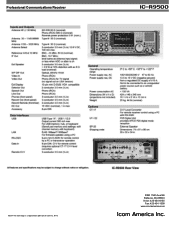
Professional Communications Receiver Range for USA**: 0.005 - 821.999999 MHz, 851 - 866.999999 MHz, 896-3335 MHz ic- r9500 **Depending on version. Full range version (0.005 - 3335 MHz) available to USA government authorized users only.
Professional Communications Receiver Range for USA**: 0.005 - 821.999999 MHz, 851 - 866.999999 MHz, 896-3335 MHz ic- r9500 **Depending on version. Full range version (0.005 - 3335 MHz) available to USA government authorized users only.
Technical Specifications
Page 4
r9500 ©2007 The Icom logo is a registered trademark of Icom Inc. 9772 2380 116th Ave NE Bellevue, WA 98004 Voice: 425-454-8155 Fax: 425-454-1509 www.icomamerica.com Professional Communications Receiver ic-
r9500 ©2007 The Icom logo is a registered trademark of Icom Inc. 9772 2380 116th Ave NE Bellevue, WA 98004 Voice: 425-454-8155 Fax: 425-454-1509 www.icomamerica.com Professional Communications Receiver ic-
Service Manual
Page 2
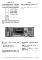
... ON for all adjustments. 5. INTRODUCTION This service manual describes the latest service information for the IC-R9500 COMMUNICATIONS RECEIVER at the time of test equipment throughly before disassembling the receiver. 2. Equipment model name and UNIT name 4. READ the instructions of publication. Icom Icom Inc. MODEL VERSION FREQUENCY COVERAGE (MHz) [USA] 0.005-821.999999, 851.000000-866.999999...
... ON for all adjustments. 5. INTRODUCTION This service manual describes the latest service information for the IC-R9500 COMMUNICATIONS RECEIVER at the time of test equipment throughly before disassembling the receiver. 2. Equipment model name and UNIT name 4. READ the instructions of publication. Icom Icom Inc. MODEL VERSION FREQUENCY COVERAGE (MHz) [USA] 0.005-821.999999, 851.000000-866.999999...

Service Manual
Page 13
The EEPROM (IC403) stores the settings for work space. An external SDRAM is routed to the whole of the IC-R9500, and processes audio signal. VIDEO, AUDIO AND USB PROCESSOR IC203 is a processor for inserted compact flash card, and its output voltage is selected from...CPU1 for LAN connection. LAN DRIVER LAN driver IC (IC404) conduct the LAN communications via the dual port SRAM (IC51). As the external I/O port for storing program, image and audio files. 3-3 LOGIC UNIT LOGIC UNIT generally controls the whole of the circuit of the receiver. • VOLTAGE BLOCK DIAGRAM AC AC-...
The EEPROM (IC403) stores the settings for work space. An external SDRAM is routed to the whole of the IC-R9500, and processes audio signal. VIDEO, AUDIO AND USB PROCESSOR IC203 is a processor for inserted compact flash card, and its output voltage is selected from...CPU1 for LAN connection. LAN DRIVER LAN driver IC (IC404) conduct the LAN communications via the dual port SRAM (IC51). As the external I/O port for storing program, image and audio files. 3-3 LOGIC UNIT LOGIC UNIT generally controls the whole of the circuit of the receiver. • VOLTAGE BLOCK DIAGRAM AC AC-...

