
Instruction Manual
Page 1
COMMUNICATIONS RECEIVER iR9500 Instruction Manual A-6553H-1EX-q Printed in Japan © 2007 Icom Inc.
COMMUNICATIONS RECEIVER iR9500 Instruction Manual A-6553H-1EX-q Printed in Japan © 2007 Icom Inc.

Instruction Manual
Page 2
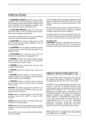
... ❍ Ultimate receiver performance: 109 dB wide dynamic range and third-order intercept (IP3) of Icom Incorporated (Japan) in relation to check you are in compliance with Icom's philosophy of personal injury, fire or electric shock. portant safety and operating instructions for making the IC-R9500 your radio of the... are registered trademarks of +40 dBm (HF bands only) ❍ 7-inch wide color TFT LCD ❍ Built-in your IC-R9500. Equipment damage may occur. No risk of "technology first." TRADEMARKS Icom, Icom Inc. Your failure to operate the receiver. i
... ❍ Ultimate receiver performance: 109 dB wide dynamic range and third-order intercept (IP3) of Icom Incorporated (Japan) in relation to check you are in compliance with Icom's philosophy of personal injury, fire or electric shock. portant safety and operating instructions for making the IC-R9500 your radio of the... are registered trademarks of +40 dBm (HF bands only) ❍ 7-inch wide color TFT LCD ❍ Built-in your IC-R9500. Equipment damage may occur. No risk of "technology first." TRADEMARKS Icom, Icom Inc. Your failure to operate the receiver. i
Instruction Manual
Page 3
...small dark or light spots. The user of Digital Voice Systems, Inc. ii If you will not use the receiver for use within this product is protected by Icom Inc., could void your ears, reduce the volume or discontinue use. This may result in any cooling vents on... an electric shock or damage to avoid inadvertent use chemical agents such as they can damage the receiver's surfaces. cohol when cleaning the IC-R9500, as benzine or al- AVOID placing the receiver against continuous high volume operation. This voice coding Technology is explicitly prohibited from the AC outlet when...
...small dark or light spots. The user of Digital Voice Systems, Inc. ii If you will not use the receiver for use within this product is protected by Icom Inc., could void your ears, reduce the volume or discontinue use. This may result in any cooling vents on... an electric shock or damage to avoid inadvertent use chemical agents such as they can damage the receiver's surfaces. cohol when cleaning the IC-R9500, as benzine or al- AVOID placing the receiver against continuous high volume operation. This voice coding Technology is explicitly prohibited from the AC outlet when...
Instruction Manual
Page 5
... gain adjustment 3-8 ■ Squelch level adjustment 3-8 ■ Audio tone adjustment 3-9 D Treble level adjustment 3-9 D Bass level adjustment 3-9 ■ Meter indication selection 3-10 D Meter type selection 3-10 RECEIVE MODES ■ Operating FM 4-2 D Convenient functions for FM 4-2 ■ Duplex operation 4-3 D Offset frequency setting 4-3 iv
... gain adjustment 3-8 ■ Squelch level adjustment 3-8 ■ Audio tone adjustment 3-9 D Treble level adjustment 3-9 D Bass level adjustment 3-9 ■ Meter indication selection 3-10 D Meter type selection 3-10 RECEIVE MODES ■ Operating FM 4-2 D Convenient functions for FM 4-2 ■ Duplex operation 4-3 D Offset frequency setting 4-3 iv
Instruction Manual
Page 6
... D Convenient functions for P25 4-18 ■ Digital squelch operation 4-19 ■ TV channel operation (except for USA versions 4-20 D Convenient functions for TV operation 4-20 RECEIVE FUNCTIONS ■ Spectrum scope screen 5-2 D Center mode 5-2 D Fix mode 5-3 D Peak marker function 5-4 D Wide band-pass filter selection 5-5 D Wide band scope function 5-5 D Mini scope screen indication...
... D Convenient functions for P25 4-18 ■ Digital squelch operation 4-19 ■ TV channel operation (except for USA versions 4-20 D Convenient functions for TV operation 4-20 RECEIVE FUNCTIONS ■ Spectrum scope screen 5-2 D Center mode 5-2 D Fix mode 5-3 D Peak marker function 5-4 D Wide band-pass filter selection 5-5 D Wide band scope function 5-5 D Mini scope screen indication...
Instruction Manual
Page 7
...; Noise reduction 5-16 ■ Notch function 5-16 ■ Autotune function 5-17 ■ AFC function 5-17 VOICE RECORDER FUNCTIONS ■ About digital voice recorder 6-2 ■ Recording a received audio 6-3 D Regular recording 6-3 ■ Playing the recorded audio 6-4 D Regular playing 6-4 ■ Erasing the recorded contents 6-4 ■ Selecting the CF memory card or USB-Memory 6-4 ■...
...; Noise reduction 5-16 ■ Notch function 5-16 ■ Autotune function 5-17 ■ AFC function 5-17 VOICE RECORDER FUNCTIONS ■ About digital voice recorder 6-2 ■ Recording a received audio 6-3 D Regular recording 6-3 ■ Playing the recorded audio 6-4 D Regular playing 6-4 ■ Erasing the recorded contents 6-4 ■ Selecting the CF memory card or USB-Memory 6-4 ■...
Instruction Manual
Page 8
... card or USB-Memory 11-23 ■ Display set (Video) mode 11-24 ■ LCD set mode 11-26 Section 12 MAINTENANCE ■ Troubleshooting 12-2 D Receiver power 12-2 D Receiving 12-2 vii
... card or USB-Memory 11-23 ■ Display set (Video) mode 11-24 ■ LCD set mode 11-26 Section 12 MAINTENANCE ■ Troubleshooting 12-2 D Receiver power 12-2 D Receiving 12-2 vii
Instruction Manual
Page 9
... 12-3 ■ Screen type selection 12-4 ■ Main dial brake adjustment 12-4 ■ Frequency calibration (approximate 12-5 ■ Opening the receiver's case 12-6 ■ Opening the shield case 12-6 ■ UT-122 installation 12-7 ■ Clock backup battery replacement 12-7 ■...setting 13-11 D Data mode with filter width setting 13-11 Section 14 SPECIFICATIONS AND OPTIONS ■ Specifications 14-2 D General 14-2 D Receiver 14-3 ■ Options 14-4 Section 15 UPDATING THE FIRMWARE ■ General 15-2 ■ Caution 15-2 ■ Preparation 15-3 D Firmware...
... 12-3 ■ Screen type selection 12-4 ■ Main dial brake adjustment 12-4 ■ Frequency calibration (approximate 12-5 ■ Opening the receiver's case 12-6 ■ Opening the shield case 12-6 ■ UT-122 installation 12-7 ■ Clock backup battery replacement 12-7 ■...setting 13-11 D Data mode with filter width setting 13-11 Section 14 SPECIFICATIONS AND OPTIONS ■ Specifications 14-2 D General 14-2 D Receiver 14-3 ■ Options 14-4 Section 15 UPDATING THE FIRMWARE ■ General 15-2 ■ Caution 15-2 ■ Preparation 15-3 D Firmware...
Instruction Manual
Page 12
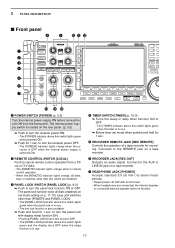
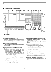
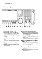
...] (p. 9-2) ➥ Push to the REMOTE jack on the rear panel. (p. 3-2) ➥ Push to turn the panel lock function ON or OFF. Connects to turn the receiver power ON. • The [POWER] indicator above this switch lights green when the timer is in use . 1 PANEL DESCRIPTION ■ Front panel i o !0 !1 !2 q w e ... when the panel lock is also available. ➥ Push and hold for 1 sec. to turn the receiver power OFF. • The [POWER] indicator lights orange when the receiver is OFF when the internal power supply is located on a tape recorder. r TIMER SWITCH [TIMER] ...
...] (p. 9-2) ➥ Push to the REMOTE jack on the rear panel. (p. 3-2) ➥ Push to turn the panel lock function ON or OFF. Connects to turn the receiver power ON. • The [POWER] indicator above this switch lights green when the timer is in use . 1 PANEL DESCRIPTION ■ Front panel i o !0 !1 !2 q w e ... when the panel lock is also available. ➥ Push and hold for 1 sec. to turn the receiver power OFF. • The [POWER] indicator lights orange when the receiver is OFF when the internal power supply is located on a tape recorder. r TIMER SWITCH [TIMER] ...
Instruction Manual
Page 13
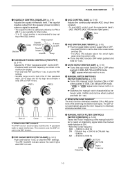
...[SQL] control. to 5100 Hz NOTCH1 NOTCH2 Lower frequency Higher frequency 1-3 The DSP circuit automatically adjusts the notch frequency to reject interference. This receiver uses the DSP circuit for the PBT function. !0 PBT CLEAR SWITCH [PBT CLEAR] (p. 5-11) Push and hold [PBT CLEAR] for...electronically modifies the IF passband width to effectively eliminate unwanted tones. The squelch disables output from the speaker (closed condition) when no signal is received. • The squelch control is ON. • Notch filter center frequency: SSB : -1060 Hz to 4040 Hz CW : CW pitch...
...[SQL] control. to 5100 Hz NOTCH1 NOTCH2 Lower frequency Higher frequency 1-3 The DSP circuit automatically adjusts the notch frequency to reject interference. This receiver uses the DSP circuit for the PBT function. !0 PBT CLEAR SWITCH [PBT CLEAR] (p. 5-11) Push and hold [PBT CLEAR] for...electronically modifies the IF passband width to effectively eliminate unwanted tones. The squelch disables output from the speaker (closed condition) when no signal is received. • The squelch control is ON. • Notch filter center frequency: SSB : -1060 Hz to 4040 Hz CW : CW pitch...
Instruction Manual
Page 15
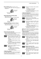
...the voice squelch control function ON and OFF; The attenuator prevents a desired signal from distorting when very strong signals are near the receiving frequency, or when very strong electric fields, such as from a broadcasting station, are near your location. ➥ Selects one...level decreases @4 TREBLE RESPONSE CONTROL [TREBLE] (inner control; in FM, FSK mode. (pgs. 4-4, 4-12) ➥ Push to the right of 2 receive RF preamps or bypasses them. (p. 5-9) ● HF bands • "P. Treble level increases Treble level decreases @5 MULTIFUNCTION SWITCHES Push to produce a constant...
...the voice squelch control function ON and OFF; The attenuator prevents a desired signal from distorting when very strong signals are near the receiving frequency, or when very strong electric fields, such as from a broadcasting station, are near your location. ➥ Selects one...level decreases @4 TREBLE RESPONSE CONTROL [TREBLE] (inner control; in FM, FSK mode. (pgs. 4-4, 4-12) ➥ Push to the right of 2 receive RF preamps or bypasses them. (p. 5-9) ● HF bands • "P. Treble level increases Treble level decreases @5 MULTIFUNCTION SWITCHES Push to produce a constant...
Instruction Manual
Page 16
... when pushed and held for 1 sec. • This function is available both in 0.1 kHz steps. ➠ To set mode settings, etc. @7 RECEIVE INDICATOR [RECEIVE] Lights green while receiving a signal and when the squelch is open. @8 TUNING STEP SWITCHES [▲UP]/[▼DOWM] (p. 3-5) ➥ Select the tuning step for 1 sec...• This indicator goes OFF, when [LOCAL] is pushed. #2 DIAL LOCK INDICATOR [LOCK] (p. 9-2) Lights orange when the dial lock function is received from a PC via the keypad, then push [YUP] or [ZDOWN]. ➥ Push and hold [▲UP] (or [▼DOWN]) for 1 sec.
... when pushed and held for 1 sec. • This function is available both in 0.1 kHz steps. ➠ To set mode settings, etc. @7 RECEIVE INDICATOR [RECEIVE] Lights green while receiving a signal and when the squelch is open. @8 TUNING STEP SWITCHES [▲UP]/[▼DOWM] (p. 3-5) ➥ Select the tuning step for 1 sec...• This indicator goes OFF, when [LOCAL] is pushed. #2 DIAL LOCK INDICATOR [LOCK] (p. 9-2) Lights orange when the dial lock function is received from a PC via the keypad, then push [YUP] or [ZDOWN]. ➥ Push and hold [▲UP] (or [▼DOWN]) for 1 sec.
Instruction Manual
Page 17
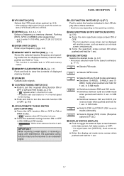
... scope screen ON or OFF. • The mini spectrum scope screen can be displayed with interference, the automatic tuning function may tune the receiver to an undesired signal. $1 LCD FUNCTION SWITCHES [F-1]-[F-7] Push to select the function indicated in CW mode. ➥ Selects FSK and FSK-R...1 sec. 1-7 SSB/CW FSK DIGITAL ➥ Selects AM and S-AM modes alternately. ➥ Switches S-AM(D), S-AM(U) and S- When receiving a weak signal, or receiving a signal with another screen, such as memory or set mode menu screen when pushed and held for 1 sec. $3 MODE SWITCHES Selects the ...
... scope screen ON or OFF. • The mini spectrum scope screen can be displayed with interference, the automatic tuning function may tune the receiver to an undesired signal. $1 LCD FUNCTION SWITCHES [F-1]-[F-7] Push to select the function indicated in CW mode. ➥ Selects FSK and FSK-R...1 sec. 1-7 SSB/CW FSK DIGITAL ➥ Selects AM and S-AM modes alternately. ➥ Switches S-AM(D), S-AM(U) and S- When receiving a weak signal, or receiving a signal with another screen, such as memory or set mode menu screen when pushed and held for 1 sec. $3 MODE SWITCHES Selects the ...
Instruction Manual
Page 18
...to select the duplex function (DUP-, DUP+ and OFF). ➥ Push and hold for 1 sec. Push and hold for 1 sec. to record the received signal until recording is ON, LEDs and LCD backlight become dim according to the preset setting. ➥ Push and hold for 1 sec. 1 PANEL DESCRIPTION ...the preset time period before [REC] was pushed. (p.6-5) • Starts recording again automatically. ➥ Regular recording; Push momentarily to record the signal received for 1 sec. %0 EXIT/SET SWITCH [EXIT/SET] ➥ Push to exit, or return to enter the offset frequency set mode menu screen...
...to select the duplex function (DUP-, DUP+ and OFF). ➥ Push and hold for 1 sec. Push and hold for 1 sec. to record the received signal until recording is ON, LEDs and LCD backlight become dim according to the preset setting. ➥ Push and hold for 1 sec. 1 PANEL DESCRIPTION ...the preset time period before [REC] was pushed. (p.6-5) • Starts recording again automatically. ➥ Regular recording; Push momentarily to record the signal received for 1 sec. %0 EXIT/SET SWITCH [EXIT/SET] ➥ Push to exit, or return to enter the offset frequency set mode menu screen...

Instruction Manual
Page 19
... and hold to open the squelch manually. • The [MONI] indicator appears on the display. • While pushing and holding this switch, release any other receiving functions such as the noise blanker or ANF. • While in a duplex operation, monitor the shifted frequency. %2 MAIN DIAL Changes the displayed frequency, selects set...
... and hold to open the squelch manually. • The [MONI] indicator appears on the display. • While pushing and holding this switch, release any other receiving functions such as the noise blanker or ANF. • While in a duplex operation, monitor the shifted frequency. %2 MAIN DIAL Changes the displayed frequency, selects set...
Instruction Manual
Page 20
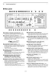
... (when the AGC function is activated or attenuator is ON. !1 VIDEO OUTPUT JACK [VIDEO OUT] Outputs video signals when TV frequencies with WFM mode are received. Connects to activate this jack when scan stopped. (p. 11-11) • Output level can be adjusted in the others set mode to the REMOTE jack...
... (when the AGC function is activated or attenuator is ON. !1 VIDEO OUTPUT JACK [VIDEO OUT] Outputs video signals when TV frequencies with WFM mode are received. Connects to activate this jack when scan stopped. (p. 11-11) • Output level can be adjusted in the others set mode to the REMOTE jack...
Instruction Manual
Page 21
...ANTENNA CONNECTOR 1 [ANT 1/HF ANT 3] (p. 2-5) Accepts a 50 Ω antenna with a Type-N connector. Can be used for transceive operation with another Icom CI-V transceiver or receiver. @9 DATA SOCKET [DATA IN] (pgs. 2-10, 2-12) Outputs LCD monitor signals (NTSC system). 1-11 Using a fuse rated for a different ...REMOTE] (p. 2-6) ➥ Connects a PC via the optional CT-17 CI-V LEVEL CONVERTER for external control of the receiver. ➥ Used for remote control of the IC-R9500 without the optional CT-17, or the FSK decoded signal output. Cuts off the AC input when over-current occurs....
...ANTENNA CONNECTOR 1 [ANT 1/HF ANT 3] (p. 2-5) Accepts a 50 Ω antenna with a Type-N connector. Can be used for transceive operation with another Icom CI-V transceiver or receiver. @9 DATA SOCKET [DATA IN] (pgs. 2-10, 2-12) Outputs LCD monitor signals (NTSC system). 1-11 Using a fuse rated for a different ...REMOTE] (p. 2-6) ➥ Connects a PC via the optional CT-17 CI-V LEVEL CONVERTER for external control of the receiver. ➥ Used for remote control of the IC-R9500 without the optional CT-17, or the FSK decoded signal output. Cuts off the AC input when over-current occurs....
Instruction Manual
Page 22
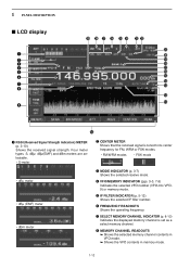
...181;, dBµ(EMF) and dBm meters are selectable. • S-meter w CENTER METER Shows that the received signal is set as a select memory channel. r VFO/MEMORY INDICATOR (pgs. 3-3, 7-3) Indicates the selected ... dBm meter e MODE INDICATOR (p. 3-7) Shows the selected receive mode. y FREQUENCY READOUTS Shows the operating frequency. 1 PANEL DESCRIPTION ■ LCD display q w e r t y u i o @9 @8 @7 @6 @5 @4 @3 @2 @1 @0 !9 !8 !7 !6 !5 !4 !3 !2 !1 !0 q RSSI (Received Signal Strength Indication) METER (p. 3-10) Shows the received signal strength. i MEMORY CHANNEL READOUTS ➥ Shows the ...
...181;, dBµ(EMF) and dBm meters are selectable. • S-meter w CENTER METER Shows that the received signal is set as a select memory channel. r VFO/MEMORY INDICATOR (pgs. 3-3, 7-3) Indicates the selected ... dBm meter e MODE INDICATOR (p. 3-7) Shows the selected receive mode. y FREQUENCY READOUTS Shows the operating frequency. 1 PANEL DESCRIPTION ■ LCD display q w e r t y u i o @9 @8 @7 @6 @5 @4 @3 @2 @1 @0 !9 !8 !7 !6 !5 !4 !3 !2 !1 !0 q RSSI (Received Signal Strength Indication) METER (p. 3-10) Shows the received signal strength. i MEMORY CHANNEL READOUTS ➥ Shows the ...

Instruction Manual
Page 25
... and frequency 2-9 ■ Monitor display connection 2-10 ■ Transceive function 2-10 ■ FSK and AFSK (SSTV) connections 2-11 ■ Accessory connector information 2-12 CAUTION!: The receiver weighs approx. 20 kg (44 lb). Always have two people available to carry, lift or turn over the...
... and frequency 2-9 ■ Monitor display connection 2-10 ■ Transceive function 2-10 ■ FSK and AFSK (SSTV) connections 2-11 ■ Accessory connector information 2-12 CAUTION!: The receiver weighs approx. 20 kg (44 lb). Always have two people available to carry, lift or turn over the...
Instruction Manual
Page 26
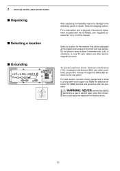
...IC-R9500, see 'Supplied accessories' on the rear panel. Make the distance between the [GND] terminal and ground as short as possible. For best results, connect a heavy gauge wire or strap to a gas or electric pipe, since the connection could cause an explosion or electric shock. 2-2 Select a location for the receiver...place in areas subject to extreme heat, cold, or vibrations, or near TV sets, radios and other problems, ground the receiver through the GROUND terminal on p. 2 INSTALLATION AND CONNECTIONS ■ Unpacking ■ Selecting a location ■ Grounding After unpacking...
...IC-R9500, see 'Supplied accessories' on the rear panel. Make the distance between the [GND] terminal and ground as short as possible. For best results, connect a heavy gauge wire or strap to a gas or electric pipe, since the connection could cause an explosion or electric shock. 2-2 Select a location for the receiver...place in areas subject to extreme heat, cold, or vibrations, or near TV sets, radios and other problems, ground the receiver through the GROUND terminal on p. 2 INSTALLATION AND CONNECTIONS ■ Unpacking ■ Selecting a location ■ Grounding After unpacking...

