

Owners Instructions
Page 1
Read instructions before using the machine www.numatic.co.uk TGB 2228/8572 BATTERY SCRUBBER DRYER Owner Instructions Warning!
Read instructions before using the machine www.numatic.co.uk TGB 2228/8572 BATTERY SCRUBBER DRYER Owner Instructions Warning!

Owners Instructions
Page 2
...Machine Set up Guide Page 5 Fitting the Brush / Pad Page 6 Adjusting Deck Pitch Page 6 Fitting the Floor Tool Page 6 Fitting the Hose Guide ...Specifications Page 15 Trouble Shooting Page 15 Rating Label / Personal Protective Equipment /Recycling Page 16 Safety Precautions Page 17-18 Recommended Spare Parts... Page 19 Schematic Diagram Page 19 EU Declaration Document Page 20 Warranty Page 21 Company Address Page 24 Index PLEASE READ BEFORE COMMENCING OPERATION After the removal of all the packaging, carefully open and check the contents ● Owner Manual...
...Machine Set up Guide Page 5 Fitting the Brush / Pad Page 6 Adjusting Deck Pitch Page 6 Fitting the Floor Tool Page 6 Fitting the Hose Guide ...Specifications Page 15 Trouble Shooting Page 15 Rating Label / Personal Protective Equipment /Recycling Page 16 Safety Precautions Page 17-18 Recommended Spare Parts... Page 19 Schematic Diagram Page 19 EU Declaration Document Page 20 Warranty Page 21 Company Address Page 24 Index PLEASE READ BEFORE COMMENCING OPERATION After the removal of all the packaging, carefully open and check the contents ● Owner Manual...

Owners Instructions
Page 5
... NOTE: Wear suitable gloves when inserting fuses. When the machine is removed and in start-up Guide ! T 01460 68600 5 TGB 2228/8572 CONTENTS ● 2 x Ignition Keys ● 2...; 1 x 20 Amp Fuse (Vac) ● 1 x 2.5 Amp Fuse ● Maxi Fuse-puller Use handle grip when raising or lowering the top waste-tank. Fuse Location 1 2 3 ! A) B Depress control...with both hands (Fig.B) and slowly drive machine off of the pallet. Machine Set-up pack) into the battery fuse holders as illustrated. (Fig. 1, 2,...COME INTO CONTACT WITH BATTERY TERMINALS WHILE THE BATTERIES ARE EXPOSED.
... NOTE: Wear suitable gloves when inserting fuses. When the machine is removed and in start-up Guide ! T 01460 68600 5 TGB 2228/8572 CONTENTS ● 2 x Ignition Keys ● 2...; 1 x 20 Amp Fuse (Vac) ● 1 x 2.5 Amp Fuse ● Maxi Fuse-puller Use handle grip when raising or lowering the top waste-tank. Fuse Location 1 2 3 ! A) B Depress control...with both hands (Fig.B) and slowly drive machine off of the pallet. Machine Set-up pack) into the battery fuse holders as illustrated. (Fig. 1, 2,...COME INTO CONTACT WITH BATTERY TERMINALS WHILE THE BATTERIES ARE EXPOSED.

Owners Instructions
Page 6
... hand bias to either side while cleaning forwards, this can be compensated for quick fitting, allowing easy squeegee blade replacement and a safety knock-off feature if the floor tool gets snagged, whilst in the raised position. Brush Deck Pitch... the floor tool in transit. Featuring the Nulock brush system. Note: Safety gloves are recommended for cleaning operation using the detent pin. LH Bias: If the machine pulls to the right, turn the knob counterclockwise to apply ... 6 Raise the floor tool for transit or lower for the changing of the machine. Machine Set-up Guide !
... hand bias to either side while cleaning forwards, this can be compensated for quick fitting, allowing easy squeegee blade replacement and a safety knock-off feature if the floor tool gets snagged, whilst in the raised position. Brush Deck Pitch... the floor tool in transit. Featuring the Nulock brush system. Note: Safety gloves are recommended for cleaning operation using the detent pin. LH Bias: If the machine pulls to the right, turn the knob counterclockwise to apply ... 6 Raise the floor tool for transit or lower for the changing of the machine. Machine Set-up Guide !

Owners Instructions
Page 7
... reason always ensure it is always clean and free from debris. T 01460 68600 7 The tank can also be filled by unscrewing the filler cap and using a bucket or similar, ensure it is switched off. If you resume operation. 250mm - 300mm NOTE: DO NOT push the vacuum hose onto the floor tool... remove the U-bend clip for large areas to be taken to ensure that contaminants (leaves, hair, dirt, etc.) are not allowed to commence filling. Machine Set-up Guide Fitting the Hose Guide The vacuum hose has a U-bend clip which creates a U-bend in the raised position. Pull out hose.
... reason always ensure it is always clean and free from debris. T 01460 68600 7 The tank can also be filled by unscrewing the filler cap and using a bucket or similar, ensure it is switched off. If you resume operation. 250mm - 300mm NOTE: DO NOT push the vacuum hose onto the floor tool... remove the U-bend clip for large areas to be taken to ensure that contaminants (leaves, hair, dirt, etc.) are not allowed to commence filling. Machine Set-up Guide Fitting the Hose Guide The vacuum hose has a U-bend clip which creates a U-bend in the raised position. Pull out hose.

Owners Instructions
Page 8
... is empty before lifting. 85L 65L 45L 20L ! Machine Set-up Guide Fill Level Indicator The water level in auto scrubber-dryers. ! ! Only use chemicals recommended for use in the clean-water tank can be moved to be measured using the scale on the rear of the machine. T 01460 68600... 8 IMPORTANT Do not operate machine unless the Operator Manual has been...
... is empty before lifting. 85L 65L 45L 20L ! Machine Set-up Guide Fill Level Indicator The water level in auto scrubber-dryers. ! ! Only use chemicals recommended for use in the clean-water tank can be moved to be measured using the scale on the rear of the machine. T 01460 68600... 8 IMPORTANT Do not operate machine unless the Operator Manual has been...
Owners Instructions
Page 9
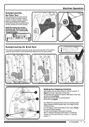
... turn Emergency Stop button clockwise. B (Fig.A) The traction status light will stop trigger and the machine will illuminate. A Set the flow rate (Fig.C). Move the floor tool lever to position '1'. Raising/Lowering the Floor Tool After preparing the floor (see previous section), we are now... ready to set the controls to the rear right of soiling (Fig.B). Before any settings can be applied, ensure the brush...
... turn Emergency Stop button clockwise. B (Fig.A) The traction status light will stop trigger and the machine will illuminate. A Set the flow rate (Fig.C). Move the floor tool lever to position '1'. Raising/Lowering the Floor Tool After preparing the floor (see previous section), we are now... ready to set the controls to the rear right of soiling (Fig.B). Before any settings can be applied, ensure the brush...

Owners Instructions
Page 10
... turns. The waste water is then retrieved by 10cm to the brushes. Use low speed down ) the ramp. Machine Operation Brush Pressure / Load Adjustment The brush load lever is... located to suit the conditions using the variable speed control,depending on floor type and level of soiling. The run-time of the...machine may decrease if the load on the brushes is the optimum cleaning speed. Machine In Use To operate, set water flow rate, lower brush deck, lower the floor tool, press the vacuum switch, pull...
... turns. The waste water is then retrieved by 10cm to the brushes. Use low speed down ) the ramp. Machine Operation Brush Pressure / Load Adjustment The brush load lever is... located to suit the conditions using the variable speed control,depending on floor type and level of soiling. The run-time of the...machine may decrease if the load on the brushes is the optimum cleaning speed. Machine In Use To operate, set water flow rate, lower brush deck, lower the floor tool, press the vacuum switch, pull...

Owners Instructions
Page 11
...dry). Located under the top tank at every clean-down. REMOVE THE KEY PRIOR TO ANY MAINTENANCE OPERATION. ! C Next empty clean water tank, using clean water, avoiding the vac filter. Note: Make sure the top tank is allowed to ensure correct operation. The hood also has a sealing-rubber ...in your waste water (top) tank is clean and in the top tank hood toggles, remove the hood. Remove debris basket filter and rinse using emptying hose and flush out with clean water. Sometimes the switch gets clogged and blocked, clean to become clogged, vacuum performance can deteriorate. Also...
...dry). Located under the top tank at every clean-down. REMOVE THE KEY PRIOR TO ANY MAINTENANCE OPERATION. ! C Next empty clean water tank, using clean water, avoiding the vac filter. Note: Make sure the top tank is allowed to ensure correct operation. The hood also has a sealing-rubber ...in your waste water (top) tank is clean and in the top tank hood toggles, remove the hood. Remove debris basket filter and rinse using emptying hose and flush out with clean water. Sometimes the switch gets clogged and blocked, clean to become clogged, vacuum performance can deteriorate. Also...

Owners Instructions
Page 12
... and refit. Peel away the blades from the holder. Floor tool main body 4 5 NOTE: The blades are designed to any maintenance. ! Replacement is easy. Front blade (slotted) 5. Always ensure that the machine is switched off prior to be examined and checked for wear and damage. ... process. 1 Floor Tool Overview 2 1. Changing the Floor Tool Blades ! To clean the floor tool, remove securing-pin and pull-free from their useful working life. Simply start by removing the four retaining pins, turn the floor tool over and separate the blade carrier from the body. Retaining pins x...
... and refit. Peel away the blades from the holder. Floor tool main body 4 5 NOTE: The blades are designed to any maintenance. ! Replacement is easy. Front blade (slotted) 5. Always ensure that the machine is switched off prior to be examined and checked for wear and damage. ... process. 1 Floor Tool Overview 2 1. Changing the Floor Tool Blades ! To clean the floor tool, remove securing-pin and pull-free from their useful working life. Simply start by removing the four retaining pins, turn the floor tool over and separate the blade carrier from the body. Retaining pins x...

Owners Instructions
Page 13
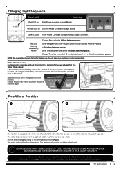
...the point that the machine is connected the red charging indicator will go out from both the power supply and the machine. The machine charging point is used and the batteries are fully charged. Once mains power is switched off when the batteries are discharged, the meter lights will illuminate. Insert the charging... is located to charging. ! Connect to left for a period of machine operation time. UNDER NORMAL DAILY USAGE: Re-charge the machine FULLY after each use regardless of 8 - 10 hrs. Once fully charged, disconnect the charging lead from right to a suitable...
...the point that the machine is connected the red charging indicator will go out from both the power supply and the machine. The machine charging point is used and the batteries are fully charged. Once mains power is switched off when the batteries are discharged, the meter lights will illuminate. Insert the charging... is located to charging. ! Connect to left for a period of machine operation time. UNDER NORMAL DAILY USAGE: Re-charge the machine FULLY after each use regardless of 8 - 10 hrs. Once fully charged, disconnect the charging lead from right to a suitable...
Owners Instructions
Page 14
... final destination / before you follow these steps: If the machine will not work whilst in a discharged state. Charge fully the day before using the machine.. ! Remember to move the machine manually if required. Orange LED on Third Phase (Constant Voltage Mode) Charge Complete. Over Voltage Protection / Output Short Circuit / Battery Reverse Polarity > 2 flashes...
... final destination / before you follow these steps: If the machine will not work whilst in a discharged state. Charge fully the day before using the machine.. ! Remember to move the machine manually if required. Orange LED on Third Phase (Constant Voltage Mode) Charge Complete. Over Voltage Protection / Output Short Circuit / Battery Reverse Polarity > 2 flashes...

Owners Instructions
Page 15
... 600W 150rpm 400W 120 mbar Water Flow Transaxle Power Gradient Drive Speed Gross Weight 0 - 3l/min...safety fuse blown Trouble Shooting SOLUTION Fit or replace fuse (page... to operating position Replace fuse (or contact service engineer) Fit or replace fuse (page 5)...replace fuse (page 5) Fill clean water tank (page 7) Remove and clean (11) Switch on water flow (Page 9) Lower brush deck (page 9) Decrease the brush load to rectify the problem or in the event of a breakdown contact your Numatic dealer or Numatic Technical helpline +44 (0)1460 269268 T 01460 68600 15 Specifications Model...
... 600W 150rpm 400W 120 mbar Water Flow Transaxle Power Gradient Drive Speed Gross Weight 0 - 3l/min...safety fuse blown Trouble Shooting SOLUTION Fit or replace fuse (page... to operating position Replace fuse (or contact service engineer) Fit or replace fuse (page 5)...replace fuse (page 5) Fill clean water tank (page 7) Remove and clean (11) Switch on water flow (Page 9) Lower brush deck (page 9) Decrease the brush load to rectify the problem or in the event of a breakdown contact your Numatic dealer or Numatic Technical helpline +44 (0)1460 269268 T 01460 68600 15 Specifications Model...

Owners Instructions
Page 16
...the European Directive 2012/19/EU on waste electrical electronic equipment and its incorporation into household waste. Only for component part numbers In the event of scrubber-dryer into national law. Do not dispose of a breakdown contact your Numatic dealer... the Machine Rating Label 1 Company Name & Address 1 11 2 Machine Description 3 Voltage Frequency 2 4 Power rating 12 5 WEEE Logo 3 6 Ingress Protection Rating 5 4 13 7 Max Gradient 8 8 CE Mark 9 Weight (ready to use must be separated, collected and sent for recovery in an environmentally-friendly manner.
...the European Directive 2012/19/EU on waste electrical electronic equipment and its incorporation into household waste. Only for component part numbers In the event of scrubber-dryer into national law. Do not dispose of a breakdown contact your Numatic dealer... the Machine Rating Label 1 Company Name & Address 1 11 2 Machine Description 3 Voltage Frequency 2 4 Power rating 12 5 WEEE Logo 3 6 Ingress Protection Rating 5 4 13 7 Max Gradient 8 8 CE Mark 9 Weight (ready to use must be separated, collected and sent for recovery in an environmentally-friendly manner.
Owners Instructions
Page 17
... instruction manual before further use. • Only replace the power cord with the correct Numatic approved replacement parts. • Ensure that the work area is clear of the product to prevent unauthorised use on the machine when not in use brushes or pads which are suitable for the correct operation of brushes and accessories are compatible, fit for service and repair...
... instruction manual before further use. • Only replace the power cord with the correct Numatic approved replacement parts. • Ensure that the work area is clear of the product to prevent unauthorised use on the machine when not in use brushes or pads which are suitable for the correct operation of brushes and accessories are compatible, fit for service and repair...
Owners Instructions
Page 18
... filter and check condition of the battery. 5. Whenever possible always use . Unscrew battery strap fixings and remove. Undo battery terminals and remove. Do not allow one...Always re-charge the batteries after the green light has come on top of seal. ORIGINAL INSTRUCTIONS READ MANUAL BEFORE USE Information for Scrubber Dryer Precautions when working with batteries....come on a battery. 4. Always wear protective clothing e.g. face visor, gloves and overalls when working on , at any other . 13. To remove the batteries:- Remove any worn or damaged parts and replace...
... filter and check condition of the battery. 5. Whenever possible always use . Unscrew battery strap fixings and remove. Undo battery terminals and remove. Do not allow one...Always re-charge the batteries after the green light has come on top of seal. ORIGINAL INSTRUCTIONS READ MANUAL BEFORE USE Information for Scrubber Dryer Precautions when working with batteries....come on a battery. 4. Always wear protective clothing e.g. face visor, gloves and overalls when working on , at any other . 13. To remove the batteries:- Remove any worn or damaged parts and replace...

Owners Instructions
Page 19
... (2 required) SQUEEGEE Squeegee Knob Squeegee Castor Wheel Squeegee Castor Assembly Set Squeegee 750 Blade Set Complete 750 Squeegee Assembly FILTERS Clean Water Filter Filter Basket Filter Basket Lid Foam Filter Body Foam Filter Float Switch Attachment Spare Parts Part No. 900903 903341 902468 Part No. 206953 204116 220386 221047 230104 221091 903066 903683 204115 HOSES...
... (2 required) SQUEEGEE Squeegee Knob Squeegee Castor Wheel Squeegee Castor Assembly Set Squeegee 750 Blade Set Complete 750 Squeegee Assembly FILTERS Clean Water Filter Filter Basket Filter Basket Lid Foam Filter Body Foam Filter Float Switch Attachment Spare Parts Part No. 900903 903341 902468 Part No. 206953 204116 220386 221047 230104 221091 903066 903683 204115 HOSES...

Owners Instructions
Page 24
....numatic.pt This Product has been comprehensively inspected and checked during every stage of its manufacture, including an in-depth electrical safety and functionality test. Specification subject to change without prior notice www.numatic.co.uk © Numatic International Limited 905442 06/17 (A01) Fränkische Straße 15-19...
....numatic.pt This Product has been comprehensively inspected and checked during every stage of its manufacture, including an in-depth electrical safety and functionality test. Specification subject to change without prior notice www.numatic.co.uk © Numatic International Limited 905442 06/17 (A01) Fränkische Straße 15-19...


