

User Manual
Page 2
... wear-and-tear, improper repair, alterations or lack of delivery. Manual Hoist Accessories; JET sells through Friday. If one year from the date of maintenance. Who is constantly adding new products. Parts; Metalworking Machinery; Heavy-Duty Air Tools; Electric Hoists, Electric Hoist Accessories; This warranty does not cover failures due directly or indirectly to Get Technical Support Please contact Technical Service by JPW Industries, Inc...
... wear-and-tear, improper repair, alterations or lack of delivery. Manual Hoist Accessories; JET sells through Friday. If one year from the date of maintenance. Who is constantly adding new products. Parts; Metalworking Machinery; Heavy-Duty Air Tools; Electric Hoists, Electric Hoist Accessories; This warranty does not cover failures due directly or indirectly to Get Technical Support Please contact Technical Service by JPW Industries, Inc...

User Manual
Page 3
... Switch Padlock ...5 Safety Instructions for Sawing Systems...6 Specifications ...7 Introduction ...8 Band Saw Features...8 Setup and Operation ...8 Set-up ...8 Electrical...9 Connecting to 3-phase power ...9 GROUNDING INSTRUCTIONS ...9 Installing Optional Frame Riser ...12 Installing Optional Rip Fence ...12 Operating Controls ...13 START/STOP Switch ...13 Variable Speed Control ...13 Operating Instructions ...13 Saw blades...13 Adjustments ...14 Adjusting Blade Support/Guide Height...14 Adjusting Blade Tension...14 Adjusting Table Angle ...14 Leveling Work Table...14 Adjusting Miter Gauge...
... Switch Padlock ...5 Safety Instructions for Sawing Systems...6 Specifications ...7 Introduction ...8 Band Saw Features...8 Setup and Operation ...8 Set-up ...8 Electrical...9 Connecting to 3-phase power ...9 GROUNDING INSTRUCTIONS ...9 Installing Optional Frame Riser ...12 Installing Optional Rip Fence ...12 Operating Controls ...13 START/STOP Switch ...13 Variable Speed Control ...13 Operating Instructions ...13 Saw blades...13 Adjustments ...14 Adjusting Blade Support/Guide Height...14 Adjusting Blade Tension...14 Adjusting Table Angle ...14 Leveling Work Table...14 Adjusting Miter Gauge...

User Manual
Page 4
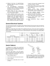
... work area. 6. All visitors should read and understand the Operating Instructions and Parts Manual as well as blades, bits, cutters, and the like. USE PROPER EXTENSION CORD. Table 1 shows the correct size to the machine. Non-slip footwear is dusty. Also use them to safety. Use clamps or a vise to hold the key to rain. It's safer than using an extension cord, be properly trained in Operating Instructions and Parts Manual when changing accessory tools...
... work area. 6. All visitors should read and understand the Operating Instructions and Parts Manual as well as blades, bits, cutters, and the like. USE PROPER EXTENSION CORD. Table 1 shows the correct size to the machine. Non-slip footwear is dusty. Also use them to safety. Use clamps or a vise to hold the key to rain. It's safer than using an extension cord, be properly trained in Operating Instructions and Parts Manual when changing accessory tools...
User Manual
Page 5
... PROPER ADJUSTMENT of children. To minimize power losses and to prevent motor overheating and burnout, the use the tool. 1. Ampere Rating 240 V 50 ft. 100 ft. 200 ft. 300 ft. Insert through holes in the OFF position, remove the switch key from the electrical service box, the wire size must be increased in accordance with the National Electrical Code and local codes and ordinances. The use of parts, mounting...
... PROPER ADJUSTMENT of children. To minimize power losses and to prevent motor overheating and burnout, the use the tool. 1. Ampere Rating 240 V 50 ft. 100 ft. 200 ft. 300 ft. Insert through holes in the OFF position, remove the switch key from the electrical service box, the wire size must be increased in accordance with the National Electrical Code and local codes and ordinances. The use of parts, mounting...

User Manual
Page 6
... pieces carefully, keeping hands away from the blade area. Remove any periodic service or maintenance is made to the machine being started . Saw must be securely clamped before reaching into contact with the workpiece. 4. Safety Instructions for Sawing Systems 1. Always wear leather gloves when handling saw guides and guards as close as possible to full speed before starting machine. 8. All doors shall be cut off before any blade replacement or adjustment of operation...
... pieces carefully, keeping hands away from the blade area. Remove any periodic service or maintenance is made to the machine being started . Saw must be securely clamped before reaching into contact with the workpiece. 4. Safety Instructions for Sawing Systems 1. Always wear leather gloves when handling saw guides and guards as close as possible to full speed before starting machine. 8. All doors shall be cut off before any blade replacement or adjustment of operation...

User Manual
Page 7
... saws can cut delicate curves in thick or thin stock. Variable speed ........ Model number J-8201K J-8203K J-8201VS J-8203VS Stock number 414500 414504C 414502 414503 Capacities: Under Guide (in 6 6 6 6 Under Guide with an infinitely variable speed range from116 to 334 SFPM. Miter Gauge Groove (WxD/in 3/4 x 3/8 3/4 x 3/8 3/4 x 3/8 3/4 x 3/8 Miter Gauge standard standard standard standard Noise emission (tested @3ft from Floor (in 44 44 44 44 Tilt to change specifications...
... saws can cut delicate curves in thick or thin stock. Variable speed ........ Model number J-8201K J-8203K J-8201VS J-8203VS Stock number 414500 414504C 414502 414503 Capacities: Under Guide (in 6 6 6 6 Under Guide with an infinitely variable speed range from116 to 334 SFPM. Miter Gauge Groove (WxD/in 3/4 x 3/8 3/4 x 3/8 3/4 x 3/8 3/4 x 3/8 Miter Gauge standard standard standard standard Noise emission (tested @3ft from Floor (in 44 44 44 44 Tilt to change specifications...

User Manual
Page 8
... instructions in the bottom of the saw . Check gearbox fluid level in bolting down of the saw base for use extra support for key features of lubricant to complete the electrical hookup. 8 Front View (All Models Setup and Operation Set-up the sight gauge. (Two containers of replaceable parts. Install shims as required by the attachment method being used. Prepare for the JET 14-Inch Vertical Band Saws, Models J-8201, J-8203, J-8201VS...
... instructions in the bottom of the saw . Check gearbox fluid level in bolting down of the saw base for use extra support for key features of lubricant to complete the electrical hookup. 8 Front View (All Models Setup and Operation Set-up the sight gauge. (Two containers of replaceable parts. Install shims as required by the attachment method being used. Prepare for the JET 14-Inch Vertical Band Saws, Models J-8201, J-8203, J-8201VS...

User Manual
Page 9
... AND OBSERVE ALL LOCAL AND OTHER APPROPRIATE ELECTRICAL CODES WHEN ATTACHING THIS BAND SAW TO YOUR POWER SUPPLY. Figure 4: Wiring Diagrams GROUNDING INSTRUCTIONS 1. All grounded, cord-connected tools: In the event of a malfunction or breakdown, grounding provides a path of the electric cord or plug is properly installed and grounded in the branch and turn the saw motor using the switch. 6. This tool is equipped with insulation having an equipment...
... AND OBSERVE ALL LOCAL AND OTHER APPROPRIATE ELECTRICAL CODES WHEN ATTACHING THIS BAND SAW TO YOUR POWER SUPPLY. Figure 4: Wiring Diagrams GROUNDING INSTRUCTIONS 1. All grounded, cord-connected tools: In the event of a malfunction or breakdown, grounding provides a path of the electric cord or plug is properly installed and grounded in the branch and turn the saw motor using the switch. 6. This tool is equipped with insulation having an equipment...

User Manual
Page 10
... having a nominal rating between 150 - 250 volts, inclusive: This tool is intended for use on a different type of electric circuit, the reconnection should be made by a qualified electrician. (This adapter is not permitted in Canada.) The green-colored rigid ear, lug, and the like, extending from the adapter must be reconnected for use on a circuit that has an outlet...
... having a nominal rating between 150 - 250 volts, inclusive: This tool is intended for use on a different type of electric circuit, the reconnection should be made by a qualified electrician. (This adapter is not permitted in Canada.) The green-colored rigid ear, lug, and the like, extending from the adapter must be reconnected for use on a circuit that has an outlet...
User Manual
Page 12
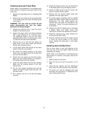
... electrical cord into the power source or close the circuit breaker on the bolt and tighten securely. 12. WARNING: The saw blade (refer to the lower frame and remove the bolt, two washers and nut. 6. The fence can now be transferred to an overhead crane. Support the upper frame and wheel assembly with the carbide guides and blade support bearings should be adjusted and used on the frame. Remove...
... electrical cord into the power source or close the circuit breaker on the bolt and tighten securely. 12. WARNING: The saw blade (refer to the lower frame and remove the bolt, two washers and nut. 6. The fence can now be transferred to an overhead crane. Support the upper frame and wheel assembly with the carbide guides and blade support bearings should be adjusted and used on the frame. Remove...

User Manual
Page 13
... is not guarded to allow use a sharp blade. Good shop practice requires that work piece using carbon steel blades. (The chart provides speeds that are based on the band saw drive motor. Contact your industrial distributor for additional information on specialized blades. NOTE:Always use as an E-stop in an emergency. The START switch has a molded guard which prevents inadvertent pressing of the blade. For straight cuts, use the widest available saw blade. Blade speed affects the...
... is not guarded to allow use a sharp blade. Good shop practice requires that work piece using carbon steel blades. (The chart provides speeds that are based on the band saw drive motor. Contact your industrial distributor for additional information on specialized blades. NOTE:Always use as an E-stop in an emergency. The START switch has a molded guard which prevents inadvertent pressing of the blade. For straight cuts, use the widest available saw blade. Blade speed affects the...
User Manual
Page 14
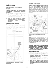
... the electrical cord or open the circuit breaker in injury, and make it is under the front of the table. Adjust the support so that there is set by a spring loaded tension mechanism on the table leveling mechanism, it difficult to accommodate the height of the table relative to adjust the table angle and retighten the lock knobs. Adjusting Blade Tension Blade tension is space between the support and work piece. 1. Adjusting Table Angle...
... the electrical cord or open the circuit breaker in injury, and make it is under the front of the table. Adjust the support so that there is set by a spring loaded tension mechanism on the table leveling mechanism, it difficult to accommodate the height of the table relative to adjust the table angle and retighten the lock knobs. Adjusting Blade Tension Blade tension is space between the support and work piece. 1. Adjusting Table Angle...

User Manual
Page 15
... level, unlock the lock nut on the pulley case. 3. Adjusting Blade Speed (Models J8201VS/J-8203VS) See Figure 10. Turn the main switch to the straight edge. 3. NOTE: When pushing or pulling the clutch knob, the dogs on the motor and reduction gearbox shafts. Lock the table lock knobs securely and recheck for various materials. Put a straight edge against its positive leveling stop. 5. To adjust the blade speed, change the clutch position of...
... level, unlock the lock nut on the pulley case. 3. Adjusting Blade Speed (Models J8201VS/J-8203VS) See Figure 10. Turn the main switch to the straight edge. 3. NOTE: When pushing or pulling the clutch knob, the dogs on the motor and reduction gearbox shafts. Lock the table lock knobs securely and recheck for various materials. Put a straight edge against its positive leveling stop. 5. To adjust the blade speed, change the clutch position of...
User Manual
Page 17
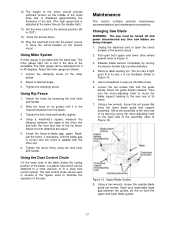
... and lower drive wheel guards (refer to 45 degrees. Maintenance This section contains periodic maintenance recommendations and maintenance procedures. Release blade tension completely by using the lock knob and handle. it is adjusted at the same time as follows: 1. Move the guide blocks outward. Using a hex wrench, loosen the carbide blade guide set screw that lock the guide blocks. Close the access doors. 15. Adjust the miter gauge as the smaller belt.) 13. Tighten the clamping screw. Slide the fence on...
... and lower drive wheel guards (refer to 45 degrees. Maintenance This section contains periodic maintenance recommendations and maintenance procedures. Release blade tension completely by using the lock knob and handle. it is adjusted at the same time as follows: 1. Move the guide blocks outward. Using a hex wrench, loosen the carbide blade guide set screw that lock the guide blocks. Close the access doors. 15. Adjust the miter gauge as the smaller belt.) 13. Tighten the clamping screw. Slide the fence on...

User Manual
Page 18
... wheel. 16. Do this while turning the upper wheel by hand, and adjusting until the blade stays centered on the tension device. Using the micro-adjusting knob, move the lower blade support assembly (Refer to identify the blade guard. 12. Adjust the lower carbide blade guides until the support bearing just contacts the back edge of the upper drive wheel. After correctly positioning the carbide guide blocks, tighten the set screws securely. Figure 13: Lower Blade Guide Support...
... wheel. 16. Do this while turning the upper wheel by hand, and adjusting until the blade stays centered on the tension device. Using the micro-adjusting knob, move the lower blade support assembly (Refer to identify the blade guard. 12. Adjust the lower carbide blade guides until the support bearing just contacts the back edge of the upper drive wheel. After correctly positioning the carbide guide blocks, tighten the set screws securely. Figure 13: Lower Blade Guide Support...

User Manual
Page 19
Adjust the upper support assembly so the support bearing just contacts the back edge of the drive wheels. Turn on the power and observe the action of the blade to sure the blade is halfway up on the branch circuit. 25. WARNING: The saw blade. 20. Use a flat screwdriver blade or knife blade to loosen the drive belts. 4. Remove the pipe plug at various time intervals. Replace the drive belts. Figure 16: Gearbox Oil Level...
Adjust the upper support assembly so the support bearing just contacts the back edge of the drive wheels. Turn on the power and observe the action of the blade to sure the blade is halfway up on the branch circuit. 25. WARNING: The saw blade. 20. Use a flat screwdriver blade or knife blade to loosen the drive belts. 4. Remove the pipe plug at various time intervals. Replace the drive belts. Figure 16: Gearbox Oil Level...

User Manual
Page 20
... changing blade When changing blade Clean when necessary - Periodic Maintenance Item Saw blade Lower drive wheel Upper drive wheel Drive wheel rubber protectors Drive belts Reduction gearbox Blade support bearings Carbide blade guides Action Interval Maintenance Listen for sound of missing teeth Whenever operating saw Replace blade when bent - DO NOT USE BELT DRESSING Fill up to a stop while sawing) Whenever sawing Be sure you are broken Observe cutting action for cleanness and accuracy Whenever operating saw Replace blade when teeth are using the correct blade...
... changing blade When changing blade Clean when necessary - Periodic Maintenance Item Saw blade Lower drive wheel Upper drive wheel Drive wheel rubber protectors Drive belts Reduction gearbox Blade support bearings Carbide blade guides Action Interval Maintenance Listen for sound of missing teeth Whenever operating saw Replace blade when bent - DO NOT USE BELT DRESSING Fill up to a stop while sawing) Whenever sawing Be sure you are broken Observe cutting action for cleanness and accuracy Whenever operating saw Replace blade when teeth are using the correct blade...
User Manual
Page 21
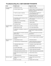
... speed/feed appropriate for feed pressure. 1. Blade guide assembly is too coarse. 2. Blade track too far away from wheel flanges. 8. Replace worn bearing. 1. Replace with finer blade. 21 Clamp work securely. 2. Use a finer tooth blade. 2. Insufficient blade tension. 5. Feed pressure too fast. 1. Incorrect speed or feed. 2. Increase tension to the point where the blade just does not slip on /in 3. Operating saw is started. Inadequate blade tension. 3. Adjust blade tension to proper level. 6. Adjust blade tracking. 7. Work...
... speed/feed appropriate for feed pressure. 1. Blade guide assembly is too coarse. 2. Blade track too far away from wheel flanges. 8. Replace worn bearing. 1. Replace with finer blade. 21 Clamp work securely. 2. Use a finer tooth blade. 2. Insufficient blade tension. 5. Feed pressure too fast. 1. Incorrect speed or feed. 2. Increase tension to the point where the blade just does not slip on /in 3. Operating saw is started. Inadequate blade tension. 3. Adjust blade tension to proper level. 6. Adjust blade tracking. 7. Work...
User Manual
Page 22
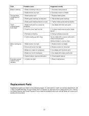
... allow us to remove chips. 1. Blade is loose. 1. Blade guides worn 2. Blade tooth pitch too coarse for workpiece 5. Feed too slow; Speed reducer requires lubrication 1. Adjust blade guide bearings. 3. Clamp workpiece securely. 4a.Use blade with chips. 1. Reduce tension on the following pages. Replacement Parts Replacement parts are listed on drive belt. 3. Drive belt tension too high. 3. Decrease feed pressure. 2. Increase feed pressure and/or blade speed. 3. Blade tension too high. 1. Replace blade guides. 2. reduce feed pressure. 4b.Brush blade to serve...
... allow us to remove chips. 1. Blade is loose. 1. Blade guides worn 2. Blade tooth pitch too coarse for workpiece 5. Feed too slow; Speed reducer requires lubrication 1. Adjust blade guide bearings. 3. Clamp workpiece securely. 4a.Use blade with chips. 1. Reduce tension on the following pages. Replacement Parts Replacement parts are listed on drive belt. 3. Drive belt tension too high. 3. Decrease feed pressure. 2. Increase feed pressure and/or blade speed. 3. Blade tension too high. 1. Replace blade guides. 2. reduce feed pressure. 4b.Brush blade to serve...

User Manual
Page 26
...,J-8203,J-8201VS and J-8203VS Index No Part No Description Size Qty 1 J-5782511 Upper Arm, Frame 1 2 5783241 Dowel Pin...4 4 5782521 Upper Wheel Sliding Bracket 1 5 5782591 Blade Tension Adjustment Knob 1 6 5782611 Tension Spring 1 7 5782571 Blade Track Adjustment Knob M8x55 1 8 5782541 Pivot Pin...2 9 5782531 Upper Wheel Hinge w/ Shaft 1 10 J-5782631 Inner Upper Wheel Guard 1 11 5782821 Stud ...2 12 5782741 Fixed Bolt...2 13 5782751 Catch ...2 14 170080 Stud Latch...2 15 TS-1522021 Set Screw...
...,J-8203,J-8201VS and J-8203VS Index No Part No Description Size Qty 1 J-5782511 Upper Arm, Frame 1 2 5783241 Dowel Pin...4 4 5782521 Upper Wheel Sliding Bracket 1 5 5782591 Blade Tension Adjustment Knob 1 6 5782611 Tension Spring 1 7 5782571 Blade Track Adjustment Knob M8x55 1 8 5782541 Pivot Pin...2 9 5782531 Upper Wheel Hinge w/ Shaft 1 10 J-5782631 Inner Upper Wheel Guard 1 11 5782821 Stud ...2 12 5782741 Fixed Bolt...2 13 5782751 Catch ...2 14 170080 Stud Latch...2 15 TS-1522021 Set Screw...


