

HT1800 Heater Owners Manual
Page 2
...an extension cord must be used only for the function it must be replaced with extension cords. Safety instructions (read the following points and be sure to the operator (electric shock, electrocution, etc.). Carefully read carefully) Every electrical device must be used , ensure that the voltage ... or inflammable liquids (gasoline, kerosene, solvents, etc.) or dust. • Do not use the device in the solution tank for instructions on the same power supply (For 15A and 20A services). Irresponsible use the hot water in an explosive atmosphere. • Do not let the device to be...
...an extension cord must be used only for the function it must be replaced with extension cords. Safety instructions (read the following points and be sure to the operator (electric shock, electrocution, etc.). Carefully read carefully) Every electrical device must be used , ensure that the voltage ... or inflammable liquids (gasoline, kerosene, solvents, etc.) or dust. • Do not use the device in the solution tank for instructions on the same power supply (For 15A and 20A services). Irresponsible use the hot water in an explosive atmosphere. • Do not let the device to be...

HT1800 Heater Owners Manual
Page 3
...the rear side of the heater into the solution tank, or it can be used to replace the solution hose of the control panel cover. Parts provided with the heater Provided with the heater you find the following parts, necessary to fix the heater on a Santoemma machine: • 2 metal brackets, to mount ...and TP18SX/DX. • 1 metal bracket, to mount the heater on the machines with model AV12QX, and AV18AX. • 2 6mm lock nuts, to mount the metal brackets to the heater. • 4 screws (M4 x 20mm), used to mount the brackets to the control panel of the 2 metal brackets, and tightening them...
...the rear side of the heater into the solution tank, or it can be used to replace the solution hose of the control panel cover. Parts provided with the heater Provided with the heater you find the following parts, necessary to fix the heater on a Santoemma machine: • 2 metal brackets, to mount ...and TP18SX/DX. • 1 metal bracket, to mount the heater on the machines with model AV12QX, and AV18AX. • 2 6mm lock nuts, to mount the metal brackets to the heater. • 4 screws (M4 x 20mm), used to mount the brackets to the control panel of the 2 metal brackets, and tightening them...
HT1800 Heater Owners Manual
Page 5
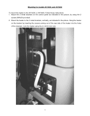
Hang the heater on the control panel as indicated in the picture, by inserting the screws coming out of the rear side of the heater into the holes of the brackets. Lock the heater using the 2 screws (M4x20) provided. 2. Mount the 2 metal brackets on the bracket by using the 2 x 6mm lock nuts. 5 Mount the heater to the AV12QX, or AV18AX, Follow these instructions: 1. Mounting for models AV12QX, and AV18AX To mount the heater to the 2 metal brackets, vertically, as indicated in the picture.
Hang the heater on the control panel as indicated in the picture, by inserting the screws coming out of the rear side of the heater into the holes of the brackets. Lock the heater using the 2 screws (M4x20) provided. 2. Mount the 2 metal brackets on the bracket by using the 2 x 6mm lock nuts. 5 Mount the heater to the AV12QX, or AV18AX, Follow these instructions: 1. Mounting for models AV12QX, and AV18AX To mount the heater to the 2 metal brackets, vertically, as indicated in the picture.

HT1800 Heater Owners Manual
Page 6
...indicates the heating element inside the heater. The main thermostat has failed and the unit now requires service. Ensure the switch for approximately 30 seconds to service the heater yourself. • Repairs may be sure that the element is sprayed normally through the accessory. 6. The high limit switch... the heater on . The water inside the heater has become hotter than 30-40 seconds, you release the spray trigger for Use 1. The heating element and other parts are illuminated. ATTENTION: • If you want to the high limit switch situated inside the heater is in the "OFF"...
...indicates the heating element inside the heater. The main thermostat has failed and the unit now requires service. Ensure the switch for approximately 30 seconds to service the heater yourself. • Repairs may be sure that the element is sprayed normally through the accessory. 6. The high limit switch... the heater on . The water inside the heater has become hotter than 30-40 seconds, you release the spray trigger for Use 1. The heating element and other parts are illuminated. ATTENTION: • If you want to the high limit switch situated inside the heater is in the "OFF"...
HT1800 Heater Owners Manual
Page 7
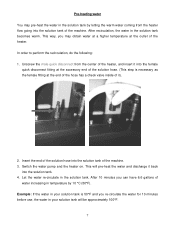
... increasing in your solution tank will pre-heat the water and discharge it ). 2. After 10 minutes you re-circulate the water for 10 minutes before use, the water in your solution tank is necessary as the female fitting at the outlet of the solution hose into the solution tank. 4. Insert the...
... increasing in your solution tank will pre-heat the water and discharge it ). 2. After 10 minutes you re-circulate the water for 10 minutes before use, the water in your solution tank is necessary as the female fitting at the outlet of the solution hose into the solution tank. 4. Insert the...

HT1800 Heater Owners Manual
Page 8
.... Add 1 quart of a deliming chemical into the solution tank. 2. Empty the solution tank and refill with the lime. (Use the same process as pre-heating the water in the solution for this process 4. NaceCare Solutions 1205 Britannia Road East Mississauga, Ontario, Canada L4W 1C7 Toll Free: 1 800 387 3210 Toll Free Fax... tank into a drain or bucket. Maintenance operations Over time, you will develop a build up of lime and calcium inside of the heating coil, follow these instructions: 1.
.... Add 1 quart of a deliming chemical into the solution tank. 2. Empty the solution tank and refill with the lime. (Use the same process as pre-heating the water in the solution for this process 4. NaceCare Solutions 1205 Britannia Road East Mississauga, Ontario, Canada L4W 1C7 Toll Free: 1 800 387 3210 Toll Free Fax... tank into a drain or bucket. Maintenance operations Over time, you will develop a build up of lime and calcium inside of the heating coil, follow these instructions: 1.
Smart Kit Installation Manual
Page 3
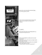
With rivets and washers provided, insert rivet into bracket/tank. Remove two screws (top right and bottom right) from coming loose** 3 Using rivet gun install rivet and make sure rivet grabs washer tightly against the tank. Hold washer on inside of top tank, use mounting bracket as shown. Attach chemical mounting bracket as shown with longer screws and washers provided with kit hardware **IF NEEDED On left side of the tank, ensuring it is held tightly against the tank. **washer prevents rivets from machine plate as a template drill through the tank.
With rivets and washers provided, insert rivet into bracket/tank. Remove two screws (top right and bottom right) from coming loose** 3 Using rivet gun install rivet and make sure rivet grabs washer tightly against the tank. Hold washer on inside of top tank, use mounting bracket as shown. Attach chemical mounting bracket as shown with longer screws and washers provided with kit hardware **IF NEEDED On left side of the tank, ensuring it is held tightly against the tank. **washer prevents rivets from machine plate as a template drill through the tank.

Smart Kit Installation Manual
Page 4
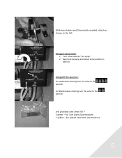
Grey holder Place threaded washer inside grey holder as shown Grey bracket holder mounted using three Philips screws provided. Bracket hardware securely fastened to top left hand side of the tank. Bracket 2. Tighten grey bracket facing away from machine. Three screws 3. Flat washer 4. Hose holder hardware 1. Mounting bracket and Hose holder installed on top left hand side of machine 4 bolt 5.
Grey holder Place threaded washer inside grey holder as shown Grey bracket holder mounted using three Philips screws provided. Bracket hardware securely fastened to top left hand side of the tank. Bracket 2. Tighten grey bracket facing away from machine. Three screws 3. Flat washer 4. Hose holder hardware 1. Mounting bracket and Hose holder installed on top left hand side of machine 4 bolt 5.
Smart Kit Installation Manual
Page 5
Jets provided with the spray bar: For restorative cleaning turn the valve to the position. For Maintenance cleaning turn the valve to the position. Turn valve towards "pre-spray" 2. Begin pre-spraying and adjust spray pattern as shown to the left. Using pre-spray mode: 1. For 3 jet wand, low moisture 1 yellow - For plastic hand tool, low moisture 5 With hose holder and 10mm bolt provided, attach as desired Using with Smart Kit ™ 3 green -
Jets provided with the spray bar: For restorative cleaning turn the valve to the position. For Maintenance cleaning turn the valve to the position. Turn valve towards "pre-spray" 2. Begin pre-spraying and adjust spray pattern as shown to the left. Using pre-spray mode: 1. For 3 jet wand, low moisture 1 yellow - For plastic hand tool, low moisture 5 With hose holder and 10mm bolt provided, attach as desired Using with Smart Kit ™ 3 green -

TP18DX Owners Manual
Page 1
... competent person and immediate action taken to rectify any faults found. Dual Motor Box Extractor Model: TP 18DX Starting Serial No. 5000 NOTE: As with all times during its use, in addition to ensuring that routine and preventative maintenance is carried out periodically in this ...respect. In particular the electrical supply cable should be exercised at all its safe operation. Failure to carry out maintenance as necessary, including replacement of parts to the ...
... competent person and immediate action taken to rectify any faults found. Dual Motor Box Extractor Model: TP 18DX Starting Serial No. 5000 NOTE: As with all times during its use, in addition to ensuring that routine and preventative maintenance is carried out periodically in this ...respect. In particular the electrical supply cable should be exercised at all its safe operation. Failure to carry out maintenance as necessary, including replacement of parts to the ...
TP18DX Owners Manual
Page 2
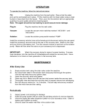
...can now be connected to remove the recovery tank from the rear of the recovery tank and replaced with a hose direct from this connector you must be filled with water via the front spout using a dirty bucket. It is held in place by four latches. you should be removed. The...inlet filter and weight. Solution Tank The solution tank is attached to the recovery tank it submerged. but - For use, the extraction hose solution line should first disconnect the power cord from below. Remove the vacuum hose entering the recovery tank from the wall outlet. At the rear of the...
...can now be connected to remove the recovery tank from the rear of the recovery tank and replaced with a hose direct from this connector you must be filled with water via the front spout using a dirty bucket. It is held in place by four latches. you should be removed. The...inlet filter and weight. Solution Tank The solution tank is attached to the recovery tank it submerged. but - For use, the extraction hose solution line should first disconnect the power cord from below. Remove the vacuum hose entering the recovery tank from the wall outlet. At the rear of the...
TP18DX Owners Manual
Page 3
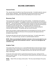
... accessory tool. Clean or replace jets if pattern is depressed. Fill: Unplug the machine from the motor fans and fan casing. Install the accessory vacuum hose at... inlet filter in the recovery tank. OPERATION To operate the machine, follow the instructions below. Plug In: Plug the machine into the solution tank an appropriate quantity ...tank and pump this through the system. Fill the machine with hot clean water using the drain valve under the machine. 2) Put some fresh water in place. ...Periodically 1) Inspect power cord and plug for 1 to avoid vacuum motor damage.
... accessory tool. Clean or replace jets if pattern is depressed. Fill: Unplug the machine from the motor fans and fan casing. Install the accessory vacuum hose at... inlet filter in the recovery tank. OPERATION To operate the machine, follow the instructions below. Plug In: Plug the machine into the solution tank an appropriate quantity ...tank and pump this through the system. Fill the machine with hot clean water using the drain valve under the machine. 2) Put some fresh water in place. ...Periodically 1) Inspect power cord and plug for 1 to avoid vacuum motor damage.
TP18DX Owners Manual
Page 4
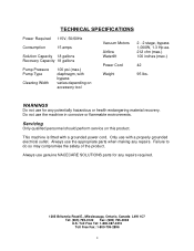
... Road E., Mississauga, Ontario, Canada L4W 1C7 Tel: (905) 795-0122 Fax: (905) 795-0038 U.S. WARNINGS Do not use genuine NACECARE SOLUTIONS parts for any repairs. Servicing Only qualified personnel should perform service on accessory tool Vacuum Motors Airflow Waterlift Power Cord Weight 2 - 2 stage, bypass 1,000W, 1.3 Hp ea. 212 cfm (max.) 100 inches (max.) 42 95 lbs. Always...
... Road E., Mississauga, Ontario, Canada L4W 1C7 Tel: (905) 795-0122 Fax: (905) 795-0038 U.S. WARNINGS Do not use genuine NACECARE SOLUTIONS parts for any repairs. Servicing Only qualified personnel should perform service on accessory tool Vacuum Motors Airflow Waterlift Power Cord Weight 2 - 2 stage, bypass 1,000W, 1.3 Hp ea. 212 cfm (max.) 100 inches (max.) 42 95 lbs. Always...


