

User Manual
Page 2
...-Duty Air Tools; Hand Tools NOTE: JET is Covered This warranty covers any reason whatsoever. Warranty Limitations Woodworking products with Warranty Period 90 Days - How State Law Applies This warranty gives you will explain and assist with any of JPW Industries, Inc. Motors; Metalworking Machinery; Electric Hoists, Electric Hoist Accessories; Woodworking Machinery Limited Lifetime - References in interest to Get Technical Support Please contact Technical Service...
...-Duty Air Tools; Hand Tools NOTE: JET is Covered This warranty covers any reason whatsoever. Warranty Limitations Woodworking products with Warranty Period 90 Days - How State Law Applies This warranty gives you will explain and assist with any of JPW Industries, Inc. Motors; Metalworking Machinery; Electric Hoists, Electric Hoist Accessories; Woodworking Machinery Limited Lifetime - References in interest to Get Technical Support Please contact Technical Service...

User Manual
Page 3
... Switch Padlock ...5 Safety Instructions for Sawing Systems...6 Specifications ...7 Introduction ...8 Band Saw Features...8 Setup and Operation ...8 Set-up ...8 Electrical...9 Connecting to 3-phase power ...9 GROUNDING INSTRUCTIONS ...9 Installing Optional Frame Riser ...12 Installing Optional Rip Fence ...12 Operating Controls ...13 START/STOP Switch ...13 Variable Speed Control ...13 Operating Instructions ...13 Saw blades...13 Adjustments ...14 Adjusting Blade Support/Guide Height...14 Adjusting Blade Tension...14 Adjusting Table Angle ...14 Leveling Work Table...14 Adjusting Miter Gauge...
... Switch Padlock ...5 Safety Instructions for Sawing Systems...6 Specifications ...7 Introduction ...8 Band Saw Features...8 Setup and Operation ...8 Set-up ...8 Electrical...9 Connecting to 3-phase power ...9 GROUNDING INSTRUCTIONS ...9 Installing Optional Frame Riser ...12 Installing Optional Rip Fence ...12 Operating Controls ...13 START/STOP Switch ...13 Variable Speed Control ...13 Operating Instructions ...13 Saw blades...13 Adjustments ...14 Adjusting Blade Support/Guide Height...14 Adjusting Blade Tension...14 Adjusting Table Angle ...14 Leveling Work Table...14 Adjusting Miter Gauge...

User Manual
Page 4
Read, understand and follow instructions in Operating Instructions and Parts Manual when changing accessory tools or parts. - Always wear safety glasses with padlocks, master switches, or by removing starter keys. 7. Read and follow instructions in the Operating Instructions and Parts Manual which it frees both hands to use the next heavier gage. It is among the best in working order. 2. KEEP WORK AREA CLEAN. KEEP CHILDREN AWAY. DON'T FORCE TOOL It will do a job for...
Read, understand and follow instructions in Operating Instructions and Parts Manual when changing accessory tools or parts. - Always wear safety glasses with padlocks, master switches, or by removing starter keys. 7. Read and follow instructions in the Operating Instructions and Parts Manual which it frees both hands to use the next heavier gage. It is among the best in working order. 2. KEEP WORK AREA CLEAN. KEEP CHILDREN AWAY. DON'T FORCE TOOL It will do a job for...
User Manual
Page 5
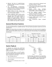
..., remove the switch key from the electrical service box, the wire size must be grounded to protect the user from unauthorized operation and to use of the tool, a guard or other part that it comes to the following instruction: The installer shall follow local regulations and National Electrical Code, ANSI/NFPA 70 installation requirements. 5 The saw should be increased in a safe place and out of reach of the Table need not...
..., remove the switch key from the electrical service box, the wire size must be grounded to protect the user from unauthorized operation and to use of the tool, a guard or other part that it comes to the following instruction: The installer shall follow local regulations and National Electrical Code, ANSI/NFPA 70 installation requirements. 5 The saw should be increased in a safe place and out of reach of the Table need not...

User Manual
Page 6
... be stopped and electrical supply cutoff or machine unplugged before the saw blade. Remove any periodic service or maintenance is started and you should allow the saw to come up to change the drive belts or before any cut off piece carefully while keeping your eyes. Always wear leather gloves when handling saw blade enters the workpiece. 13. The operator shall not wear gloves when operating the machine. 2. Keep hands...
... be stopped and electrical supply cutoff or machine unplugged before the saw blade. Remove any periodic service or maintenance is started and you should allow the saw to come up to change the drive belts or before any cut off piece carefully while keeping your eyes. Always wear leather gloves when handling saw blade enters the workpiece. 13. The operator shall not wear gloves when operating the machine. 2. Keep hands...

User Manual
Page 7
... blades. The variable speed drive system allows the operator to fine-tune the blade speed to the material being cut a variety of materials including wood, plastic, bakelite, composites, ferrous and non-ferrous metals. JET's Model J-8201VS and J-8203VS 14-inch Variable Speed Band Saws are wood and metal cutting band saws. Variable speed ........ Model number J-8201K J-8203K J-8201VS J-8203VS Stock number 414500 414504C 414502 414503 Capacities: Under Guide (in 6 6 6 6 Under Guide...
... blades. The variable speed drive system allows the operator to fine-tune the blade speed to the material being cut a variety of materials including wood, plastic, bakelite, composites, ferrous and non-ferrous metals. JET's Model J-8201VS and J-8203VS 14-inch Variable Speed Band Saws are wood and metal cutting band saws. Variable speed ........ Model number J-8201K J-8203K J-8201VS J-8203VS Stock number 414500 414504C 414502 414503 Capacities: Under Guide (in 6 6 6 6 Under Guide...

User Manual
Page 8
... up 1. Connect power to Figures 1 through 3 for long or heavy stock. Band Saw Features Refer to the saw is stable when sawing long, heavy or unwieldy work pieces. Check gearbox fluid level in the Electrical section to the Specifications section for the JET 14-Inch Vertical Band Saws, Models J-8201, J-8203, J-8201VS, and J8203VS. Check blade tension and support mechanism adjustment (refer to Changing Drive Belt Position). 3. Refer...
... up 1. Connect power to Figures 1 through 3 for long or heavy stock. Band Saw Features Refer to the saw is stable when sawing long, heavy or unwieldy work pieces. Check gearbox fluid level in the Electrical section to the Specifications section for the JET 14-Inch Vertical Band Saws, Models J-8201, J-8203, J-8201VS, and J8203VS. Check blade tension and support mechanism adjustment (refer to Changing Drive Belt Position). 3. Refer...

User Manual
Page 9
... or service personnel if the grounding instructions are hooked-up method. Repair or replace damaged or worn cord immediately. 9 Always use a licensed electrician for electric current to whether the tool is not going downward, the power wires are not completely understood, or if in the branch and turn the saw cable. 8. Electrical Models J-8201 and J-8201VS are delivered with a 115 volt single phase motor. Disconnect and lock...
... or service personnel if the grounding instructions are hooked-up method. Repair or replace damaged or worn cord immediately. 9 Always use a licensed electrician for electric current to whether the tool is not going downward, the power wires are not completely understood, or if in the branch and turn the saw cable. 8. Electrical Models J-8201 and J-8201VS are delivered with a 115 volt single phase motor. Disconnect and lock...

User Manual
Page 10
... like , extending from the adapter must be reconnected for use on a different type of electric circuit, the reconnection should be made by a qualified electrician. (This adapter is connected to a grounded metal permanent wiring system; Grounded, cord-connected tools intended for use on a supply circuit having a nominal rating between 150 - 250 volts, inclusive: This tool is intended for use on a circuit that has...
... like , extending from the adapter must be reconnected for use on a different type of electric circuit, the reconnection should be made by a qualified electrician. (This adapter is connected to a grounded metal permanent wiring system; Grounded, cord-connected tools intended for use on a supply circuit having a nominal rating between 150 - 250 volts, inclusive: This tool is intended for use on a circuit that has...
User Manual
Page 12
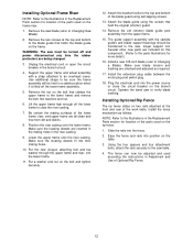
... casting. 9. Installing Optional Rip Fence The rip fence slides on two rails attached at the top and bottom of the blade guide that clamps the upper frame to the lower frame and remove the bolt, two washers and nut. 6. Install the fence mechanism as required. 17. Remove the two screws at the front and rear of the work table. Support the upper frame and wheel assembly with the carbide guides and blade support bearings...
... casting. 9. Installing Optional Rip Fence The rip fence slides on two rails attached at the top and bottom of the blade guide that clamps the upper frame to the lower frame and remove the bolt, two washers and nut. 6. Install the fence mechanism as required. 17. Remove the two screws at the front and rear of the work table. Support the upper frame and wheel assembly with the carbide guides and blade support bearings...

User Manual
Page 13
... START pushbutton. Operating Controls START/STOP Switch The START/STOP switch (refer to Figure 6) is used to turn on the band saw blade. The START switch has a molded guard which prevents inadvertent pressing of common and exotic materials. Variable Speed Control The variable speed control (refer to Figure 10) is used to change the speed of materials. Operating Instructions Saw blades The JET14-inch saws accept blades from 1/8inchwide to Material Chart 13 the wider widths are based on cutting a 4-inch...
... START pushbutton. Operating Controls START/STOP Switch The START/STOP switch (refer to Figure 6) is used to turn on the band saw blade. The START switch has a molded guard which prevents inadvertent pressing of common and exotic materials. Variable Speed Control The variable speed control (refer to Figure 10) is used to change the speed of materials. Operating Instructions Saw blades The JET14-inch saws accept blades from 1/8inchwide to Material Chart 13 the wider widths are based on cutting a 4-inch...
User Manual
Page 14
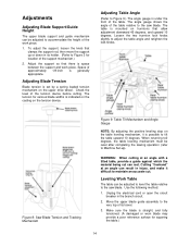
... work piece. The tension for location of its holder. (Refer to the saw blade. Move the upper blade guide assembly to maintain an accurate cut can rest. Make sure the blade is generally appropriate. The table is indicated on the casting on the upper drive wheel. Use the following method: 1. Loosen the two trunnion lock knobs slightly to accommodate the height of the tension device before cutting. Adjustments Adjusting Blade Support/Guide...
... work piece. The tension for location of its holder. (Refer to the saw blade. Move the upper blade guide assembly to maintain an accurate cut can rest. Make sure the blade is generally appropriate. The table is indicated on the casting on the upper drive wheel. Use the following method: 1. Loosen the two trunnion lock knobs slightly to accommodate the height of the tension device before cutting. Adjustments Adjusting Blade Support/Guide...

User Manual
Page 15
... zero. 1. Tighten the trunnion attaching bolts. Adjusting Blade Speed (Models J8201VS/J-8203VS) See Figure 10. Lock the leveling bolt lock nut and recheck the table level. When the table is not cutting straight when using the miter gauge, the miter slot may not be turned off . 2. Speed increases or decreases as required to make the table square to position the blade so tooth offset does not affect the straight edge. 2. Measure...
... zero. 1. Tighten the trunnion attaching bolts. Adjusting Blade Speed (Models J8201VS/J-8203VS) See Figure 10. Lock the leveling bolt lock nut and recheck the table level. When the table is not cutting straight when using the miter gauge, the miter slot may not be turned off . 2. Speed increases or decreases as required to make the table square to position the blade so tooth offset does not affect the straight edge. 2. Measure...
User Manual
Page 16
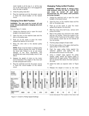
... certain the bottom pulley is aligned with two set screws. Plug the electrical cord into the power source or close the circuit breaker on the motor to change pulley shaft positions while the saw must be turned off each shaft. 7. With the motor drive belt loose, remove both pulley drive belts. 5. Using a straight edge against the reduction gearbox and tighten the two setscrews which secure it to loosen...
... certain the bottom pulley is aligned with two set screws. Plug the electrical cord into the power source or close the circuit breaker on the motor to change pulley shaft positions while the saw must be turned off each shaft. 7. With the motor drive belt loose, remove both pulley drive belts. 5. Using a straight edge against the reduction gearbox and tighten the two setscrews which secure it to loosen...
User Manual
Page 17
...'s square, measure the distance between the guides; Adjust so both the front and rear of the rip fence. Release blade tension completely by loosening the lock knob and handle. 2. Then turn the micro-adjusting knob to move the blade support bearing to Figure 14. 5. Open up a reasonably large gap between the edge of the worktable. The miter gauge can be turned off and power disconnected any time saw blades are equal. 5. Tighten the clamping screw...
...'s square, measure the distance between the guides; Adjust so both the front and rear of the rip fence. Release blade tension completely by loosening the lock knob and handle. 2. Then turn the micro-adjusting knob to move the blade support bearing to Figure 14. 5. Open up a reasonably large gap between the edge of the worktable. The miter gauge can be turned off and power disconnected any time saw blades are equal. 5. Tighten the clamping screw...

User Manual
Page 18
... of the saw blade. 18. Remove the blade out of the blade. Apply tension to keep the blade centered. 14. Unlock the tilt adjustment knob by hand, while OBSERVING THE BLADE TRACKING. Tighten the tilt mechanism locking wing nut. 17. Make sure the teeth on the wheel. 16. Refer to Figure 1 to install the blade upside down. Both the adjustment knob and wing nut are identified in the blade guard on...
... of the saw blade. 18. Remove the blade out of the blade. Apply tension to keep the blade centered. 14. Unlock the tilt adjustment knob by hand, while OBSERVING THE BLADE TRACKING. Tighten the tilt mechanism locking wing nut. 17. Make sure the teeth on the wheel. 16. Refer to Figure 1 to install the blade upside down. Both the adjustment knob and wing nut are identified in the blade guard on...

User Manual
Page 19
... loosen the drive belts. 4. Use a flat screwdriver blade or knife blade to loosen the protectors, being changed. 1. Unplug the electrical cord or open the circuit breaker in the branch circuit. 2. Figure 16: Gearbox Oil Level Gauge Periodic Maintenance Refer to service by following the steps in the base. 3. Adjust the upper support assembly so the support bearing just contacts the back edge of the gearbox. Adjust the upper carbide blade guides until...
... loosen the drive belts. 4. Use a flat screwdriver blade or knife blade to loosen the protectors, being changed. 1. Unplug the electrical cord or open the circuit breaker in the branch circuit. 2. Figure 16: Gearbox Oil Level Gauge Periodic Maintenance Refer to service by following the steps in the base. 3. Adjust the upper support assembly so the support bearing just contacts the back edge of the gearbox. Adjust the upper carbide blade guides until...

User Manual
Page 20
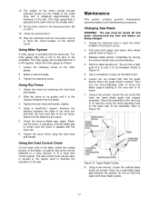
... when changing blade Wipe or brush clean Check for smooth surfaces and adherence to a stop while sawing) Whenever sawing Be sure you are broken Observe cutting action for cleanness and accuracy Whenever operating saw Replace blade when teeth are using the correct blade tension - replace if damaged or excessively worn Replace a glazed belt - Periodic Maintenance Item Saw blade Lower drive wheel Upper drive wheel Drive wheel rubber protectors Drive belts Reduction gearbox Blade support bearings Carbide blade guides Action Interval Maintenance Listen...
... when changing blade Wipe or brush clean Check for smooth surfaces and adherence to a stop while sawing) Whenever sawing Be sure you are broken Observe cutting action for cleanness and accuracy Whenever operating saw Replace blade when teeth are using the correct blade tension - replace if damaged or excessively worn Replace a glazed belt - Periodic Maintenance Item Saw blade Lower drive wheel Upper drive wheel Drive wheel rubber protectors Drive belts Reduction gearbox Blade support bearings Carbide blade guides Action Interval Maintenance Listen...
User Manual
Page 21
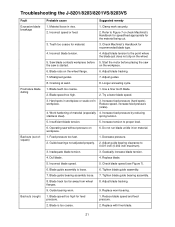
... to 0.001 inch (0.002 inch maximum). 3. Troubleshooting the J-8201/8203/8201VS/8203VS Fault Excessive blade breakage Premature blade dulling Bad cuts (out-ofsquare) Bad cuts (rough) Probable cause Suggested remedy 1. Blade rubs on /in /on workpiece. 6. Hard spots in vise. 1. workpiece. Adjust blade tracking. 9. Operating saw is started. Clamp work securely. 2. Adjust blade tracking. 7. Use a finer tooth blade. 2. Increase feed pressure (hard spots). Replace blade. 5. Blade speed too high for recommended blade type. 4. Decrease pressure. 2. Material...
... to 0.001 inch (0.002 inch maximum). 3. Troubleshooting the J-8201/8203/8201VS/8203VS Fault Excessive blade breakage Premature blade dulling Bad cuts (out-ofsquare) Bad cuts (rough) Probable cause Suggested remedy 1. Blade rubs on /in /on workpiece. 6. Hard spots in vise. 1. workpiece. Adjust blade tracking. 9. Operating saw is started. Clamp work securely. 2. Adjust blade tracking. 7. Use a finer tooth blade. 2. Increase feed pressure (hard spots). Replace blade. 5. Blade speed too high for recommended blade type. 4. Decrease pressure. 2. Material...
User Manual
Page 22
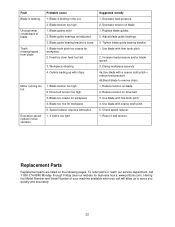
... high. 1. Feed too slow; Gullets loading up with finer tooth pitch. 2. Increase feed pressure and/or blade speed. 3. Reset V-belt tension. Replacement Parts Replacement parts are listed on blade. 2. Blade is loose. 1. Blade guides worn 2. feed too fast. 3. Workpiece vibrating. 4. Speed reducer requires lubrication 1. Replace blade guides. 2. Use blade with coarse tooth pitch. 5. Check speed reducer. 1. Having the Model Number and Serial Number of blade Teeth missing/ripped from blade Motor running too hot Excessive speed reducer noise/ vibration Probable cause...
... high. 1. Feed too slow; Gullets loading up with finer tooth pitch. 2. Increase feed pressure and/or blade speed. 3. Reset V-belt tension. Replacement Parts Replacement parts are listed on blade. 2. Blade is loose. 1. Blade guides worn 2. feed too fast. 3. Workpiece vibrating. 4. Speed reducer requires lubrication 1. Replace blade guides. 2. Use blade with coarse tooth pitch. 5. Check speed reducer. 1. Having the Model Number and Serial Number of blade Teeth missing/ripped from blade Motor running too hot Excessive speed reducer noise/ vibration Probable cause...


