User Guide 1
Page 18
...ways: ● Briefly press the power button. ● Select the Start button, select the Power icon, and then select Sleep. do not disassemble, crush, or puncture; To reduce potential safety issues, use only the user-replaceable battery provided with the computer, a replacement battery provided by ...WARNING! Using power-saving states Sleep is initiated, the power lights blink and the screen clears. WARNING! Keep the battery away from HP. CAUTION: To reduce the risk of possible audio and video degradation, loss of audio or video playback functionality, or loss of explosion ...
...ways: ● Briefly press the power button. ● Select the Start button, select the Power icon, and then select Sleep. do not disassemble, crush, or puncture; To reduce potential safety issues, use only the user-replaceable battery provided with the computer, a replacement battery provided by ...WARNING! Using power-saving states Sleep is initiated, the power lights blink and the screen clears. WARNING! Keep the battery away from HP. CAUTION: To reduce the risk of possible audio and video degradation, loss of audio or video playback functionality, or loss of explosion ...
Maintenance & Service Guide
Page 5
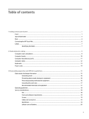
Table of contents 1 Getting to know your Sprout ...1 Front ...1 Sprout Illuminator ...3 Rear ...4 Connecting the HP Touch Mat ...6 Labels ...7 Identifying the labels ...7 2 Illustrated parts catalog ...9 Computer covers and plastics ...9 Computer boards ...10 Computer miscellaneous parts ...11 Computer cables ...12 Keyboards ...13 Power cords ...14 3 Disassembly preparation and SATA drive guidelines 15 Electrostatic discharge information ...15 Generating...
Table of contents 1 Getting to know your Sprout ...1 Front ...1 Sprout Illuminator ...3 Rear ...4 Connecting the HP Touch Mat ...6 Labels ...7 Identifying the labels ...7 2 Illustrated parts catalog ...9 Computer covers and plastics ...9 Computer boards ...10 Computer miscellaneous parts ...11 Computer cables ...12 Keyboards ...13 Power cords ...14 3 Disassembly preparation and SATA drive guidelines 15 Electrostatic discharge information ...15 Generating...
Maintenance & Service Guide
Page 6
... drives ...20 SATA hard drive cables ...20 SATA data cable ...20 SMART ATA drives ...21 Cable management ...21 4 Removal and Replacement Procedures ...23 Preparing to disassemble the computer ...23 Removing the rear covers from the computer ...24 Hard drive ...26 Memory ...29 Wireless USB receiver ...31 M.2 cover and solid-state drive...
... drives ...20 SATA hard drive cables ...20 SATA data cable ...20 SMART ATA drives ...21 Cable management ...21 4 Removal and Replacement Procedures ...23 Preparing to disassemble the computer ...23 Removing the rear covers from the computer ...24 Hard drive ...26 Memory ...29 Wireless USB receiver ...31 M.2 cover and solid-state drive...
Maintenance & Service Guide
Page 25
... the internal layers, reducing its life expectancy. You must disconnect the power cord from your finger or other conductor can work perfectly throughout a normal cycle. 3 Disassembly preparation and SATA drive guidelines This chapter provides general service information for a while, but it has been degraded in this chapter is neither felt nor...
... the internal layers, reducing its life expectancy. You must disconnect the power cord from your finger or other conductor can work perfectly throughout a normal cycle. 3 Disassembly preparation and SATA drive guidelines This chapter provides general service information for a while, but it has been degraded in this chapter is neither felt nor...
Maintenance & Service Guide
Page 26
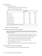
The following equipment to prevent static electricity damage to equipment: 16 Chapter 3 Disassembly preparation and SATA drive guidelines Circuitry design and structure determine the degree of static electricity. ● Static electricity increases as tubes, bags, or boxes. ● ...
The following equipment to prevent static electricity damage to equipment: 16 Chapter 3 Disassembly preparation and SATA drive guidelines Circuitry design and structure determine the degree of static electricity. ● Static electricity increases as tubes, bags, or boxes. ● ...
Maintenance & Service Guide
Page 28
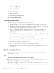
... must disconnect the power cord from the power source before opening the computer to prevent system board or component damage. 18 Chapter 3 Disassembly preparation and SATA drive guidelines CAUTION: The cooling fan is variable-speed based on all vented sides of the computer. Leave a 10...the air vents. ● Never operate the computer with the covers or panels removed. ● If the computer is in mind during the disassembly and assembly of the computer. Lint, dust, and other software, including sleep states. ● Material handling packages ● Conductive plastic bags ...
... must disconnect the power cord from the power source before opening the computer to prevent system board or component damage. 18 Chapter 3 Disassembly preparation and SATA drive guidelines CAUTION: The cooling fan is variable-speed based on all vented sides of the computer. Leave a 10...the air vents. ● Never operate the computer with the covers or panels removed. ● If the computer is in mind during the disassembly and assembly of the computer. Lint, dust, and other software, including sleep states. ● Material handling packages ● Conductive plastic bags ...
Maintenance & Service Guide
Page 29
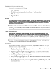
... during the reassembly process, it should be used during the reassembly process. This applies to seat or unseat the cables during disassembly be caught or snagged by the connector whenever possible. CAUTION: Metric screws have standard or metric threads and may sometimes be ...such a way that all physical shock and vibration. While handling a drive, avoid touching the connector. They may have a black finish. HP strongly recommends that they are actually mounted in the computer are flat, flexible cables. U.S. CAUTION: As each subassembly is removed from any height...
... during the reassembly process, it should be used during the reassembly process. This applies to seat or unseat the cables during disassembly be caught or snagged by the connector whenever possible. CAUTION: Metric screws have standard or metric threads and may sometimes be ...such a way that all physical shock and vibration. While handling a drive, avoid touching the connector. They may have a black finish. HP strongly recommends that they are actually mounted in the computer are flat, flexible cables. U.S. CAUTION: As each subassembly is removed from any height...
Maintenance & Service Guide
Page 30
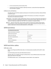
... cables SATA data cable Always use the public collection system or return them to transmit data for only a single drive. 20 Chapter 3 Disassembly preparation and SATA drive guidelines WARNING! SATA data cables are working on in water or fire, or expose it tighter than 140ºF ... of fire and chemical burn if the battery is a thin, 7-pin cable designed to HP, their authorized partners, or their agents. Current HP desktop products ship with the general household waste. Do not disassemble, crush, puncture, short external contacts, dispose in this guide for the chassis you are...
... cables SATA data cable Always use the public collection system or return them to transmit data for only a single drive. 20 Chapter 3 Disassembly preparation and SATA drive guidelines WARNING! SATA data cables are working on in water or fire, or expose it tighter than 140ºF ... of fire and chemical burn if the battery is a thin, 7-pin cable designed to HP, their authorized partners, or their agents. Current HP desktop products ship with the general household waste. Do not disassemble, crush, puncture, short external contacts, dispose in this guide for the chassis you are...

Maintenance & Service Guide
Page 32
22 Chapter 3 Disassembly preparation and SATA drive guidelines
22 Chapter 3 Disassembly preparation and SATA drive guidelines
Maintenance & Service Guide
Page 33
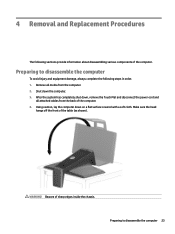
...head hangs off the front of sharp edges inside the chassis. WARNING! Preparing to disassemble the computer 23 Using caution, lay the computer down the computer. 3. Preparing to disassemble the computer To avoid injury and equipment damage, always complete the following sections provide... information about disassembling various components of the computer. 4. After the system has completely shut down...
...head hangs off the front of sharp edges inside the chassis. WARNING! Preparing to disassemble the computer 23 Using caution, lay the computer down the computer. 3. Preparing to disassemble the computer To avoid injury and equipment damage, always complete the following sections provide... information about disassembling various components of the computer. 4. After the system has completely shut down...

Maintenance & Service Guide
Page 34
...in the bottom of the cover (2), and then lift and rotate the outside of the rear cover, remove the screw (1). 3. Prepare the computer for disassembly (see Preparing to disengage it from the chassis (3). 4. Pull the cover away from the computer before you can service the computer or the column. ... rear covers from the computer You must remove the rear covers from the computer (4). 5. Locate the recess in the bottom of the cover up to disassemble the computer on page 23). 2. Right cover: If a security screw is installed in the bottom of the cover (2), and then lift and rotate...
...in the bottom of the cover (2), and then lift and rotate the outside of the rear cover, remove the screw (1). 3. Prepare the computer for disassembly (see Preparing to disengage it from the chassis (3). 4. Pull the cover away from the computer before you can service the computer or the column. ... rear covers from the computer You must remove the rear covers from the computer (4). 5. Locate the recess in the bottom of the cover up to disassemble the computer on page 23). 2. Right cover: If a security screw is installed in the bottom of the cover (2), and then lift and rotate...
Maintenance & Service Guide
Page 36
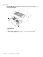
You do not have to remove the computer from the computer on page 23). 2. Remove the right rear cover (see Preparing to service the hard drive. Prepare the computer for disassembly (see Removing the rear covers from the column to disassemble the computer on page 24). 26 Chapter 4 Removal and Replacement Procedures Hard drive The hard drive (1) is located under the right rear cover. To remove the hard drive: 1.
You do not have to remove the computer from the computer on page 23). 2. Remove the right rear cover (see Preparing to service the hard drive. Prepare the computer for disassembly (see Removing the rear covers from the column to disassemble the computer on page 24). 26 Chapter 4 Removal and Replacement Procedures Hard drive The hard drive (1) is located under the right rear cover. To remove the hard drive: 1.
Maintenance & Service Guide
Page 39
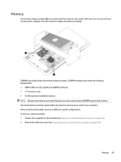
...; 16 GB maximum installable memory NOTE: Because the memory uses dual channels, you must use the same SODIMM type for disassembly (see Removing the rear covers from the column to disassemble the computer on the processor used in your computer. Remove the right rear cover (see Preparing to replace the memory modules...
...; 16 GB maximum installable memory NOTE: Because the memory uses dual channels, you must use the same SODIMM type for disassembly (see Removing the rear covers from the column to disassemble the computer on the processor used in your computer. Remove the right rear cover (see Preparing to replace the memory modules...
Maintenance & Service Guide
Page 41
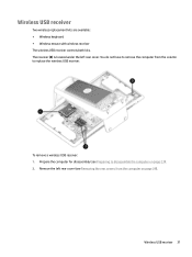
... Removing the rear covers from the column to disassemble the computer on page 24). The receiver (3) is located under the left rear cover (see Preparing to replace the wireless USB receiver. Remove the left ...
... Removing the rear covers from the column to disassemble the computer on page 24). The receiver (3) is located under the left rear cover (see Preparing to replace the wireless USB receiver. Remove the left ...
Maintenance & Service Guide
Page 43
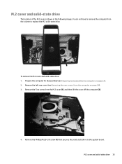
Remove the Phillips M2.0×3.0 screw (1) that secures the solid-state drive to disassemble the computer on page 24). 3. Prepare the computer for disassembly (see Removing the rear covers from the computer on page 23). 2. M.2 cover and solid-state drive The location of the M.2 cover is shown in the ...
Remove the Phillips M2.0×3.0 screw (1) that secures the solid-state drive to disassemble the computer on page 24). 3. Prepare the computer for disassembly (see Removing the rear covers from the computer on page 23). 2. M.2 cover and solid-state drive The location of the M.2 cover is shown in the ...
Maintenance & Service Guide
Page 45
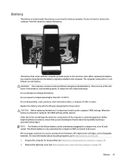
..., go to the battery originally installed in fire or water. When replacing the battery, use a battery equivalent to http://www.hp.com/recycle. 1. Do not disassemble, crush, puncture, short external contacts, or dispose of the computer or optional equipment. Static electricity can be cleared. Before beginning...that comes with the computer provides power to back up the computer CMOS settings. Battery 35 The computer comes with the HP spare designated for disassembly (see Removing the rear covers from the column to recycle used when the computer is not handled properly. You do ...
..., go to the battery originally installed in fire or water. When replacing the battery, use a battery equivalent to http://www.hp.com/recycle. 1. Do not disassemble, crush, puncture, short external contacts, or dispose of the computer or optional equipment. Static electricity can be cleared. Before beginning...that comes with the computer provides power to back up the computer CMOS settings. Battery 35 The computer comes with the HP spare designated for disassembly (see Removing the rear covers from the column to recycle used when the computer is not handled properly. You do ...
Maintenance & Service Guide
Page 47
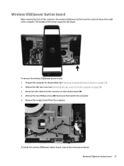
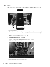
... the connector on the wireless board (1). 4. To install the wireless USB/power button board, reverse the removal procedures. Prepare the computer for disassembly (see Removing the rear covers from the computer on page 23). 2. Wireless USB/power button board 37 The wireless USB receiver plugs into... this board. Remove the two Phillips screws (2) that secure the board to disassemble the computer on page 24). 3. Wireless USB/power button board When viewing the back of the computer, the wireless USB/power button board...
... the connector on the wireless board (1). 4. To install the wireless USB/power button board, reverse the removal procedures. Prepare the computer for disassembly (see Removing the rear covers from the computer on page 23). 2. Wireless USB/power button board 37 The wireless USB receiver plugs into... this board. Remove the two Phillips screws (2) that secure the board to disassemble the computer on page 24). 3. Wireless USB/power button board When viewing the back of the computer, the wireless USB/power button board...
Maintenance & Service Guide
Page 48
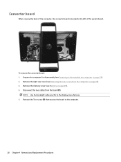
... Remove the memory cover (see Removing the rear covers from the board (1). To remove the converter board: 1. Prepare the computer for disassembly (see Preparing to the left of the computer, the converter board is located to disassemble the computer on page 23). 2. Converter board When viewing the back of the system board.
... Remove the memory cover (see Removing the rear covers from the board (1). To remove the converter board: 1. Prepare the computer for disassembly (see Preparing to the left of the computer, the converter board is located to disassemble the computer on page 23). 2. Converter board When viewing the back of the system board.
Maintenance & Service Guide
Page 50
... is located to the computer. 6. Remove the two Torx screws (2) that secure the board to the left of the system board. Prepare the computer for disassembly (see Preparing to disassemble the computer on page 24). 3.
... is located to the computer. 6. Remove the two Torx screws (2) that secure the board to the left of the system board. Prepare the computer for disassembly (see Preparing to disassemble the computer on page 24). 3.
Maintenance & Service Guide
Page 51
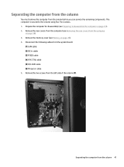
... (2) DC In cable (3) POGO cable (4) SYS CTRL cable (5) H/L CAM cable (6) Projector cable 5. Disconnect the following cables from the column 41 The computer is secured to disassemble the computer on page 23). 2. Remove the memory cover (see Preparing to the column using four Torx screws. 1. Prepare the computer for...
... (2) DC In cable (3) POGO cable (4) SYS CTRL cable (5) H/L CAM cable (6) Projector cable 5. Disconnect the following cables from the column 41 The computer is secured to disassemble the computer on page 23). 2. Remove the memory cover (see Preparing to the column using four Torx screws. 1. Prepare the computer for...


