User Guide 1
Page 18
...you stopped working. do not initiate Sleep while reading from or writing to a disc or an external memory card. Your work is replaced by HP, or a compatible battery purchased from children. To exit Sleep, briefly press the power button. NOTE: If you have set a password to the... power User-replaceable battery notices WARNING! To reduce the risk of explosion if battery is saved to the instructions. do not disassemble, crush, or puncture; WARNING! NOTE: You cannot initiate any type of networking connection or perform any of used batteries according to memory.
...you stopped working. do not initiate Sleep while reading from or writing to a disc or an external memory card. Your work is replaced by HP, or a compatible battery purchased from children. To exit Sleep, briefly press the power button. NOTE: If you have set a password to the... power User-replaceable battery notices WARNING! To reduce the risk of explosion if battery is saved to the instructions. do not disassemble, crush, or puncture; WARNING! NOTE: You cannot initiate any type of networking connection or perform any of used batteries according to memory.
Maintenance & Service Guide
Page 5
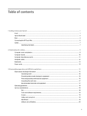
Table of contents 1 Getting to know your Sprout ...1 Front ...1 Sprout Illuminator ...3 Rear ...4 Connecting the HP Touch Mat ...6 Labels ...7 Identifying the labels ...7 2 Illustrated parts catalog ...9 Computer covers and plastics ...9 Computer boards ...10 Computer miscellaneous parts ...11 Computer cables ...12 Keyboards ...13 Power cords ...14 3 Disassembly preparation and SATA drive guidelines 15 Electrostatic discharge information ...15 Generating...
Table of contents 1 Getting to know your Sprout ...1 Front ...1 Sprout Illuminator ...3 Rear ...4 Connecting the HP Touch Mat ...6 Labels ...7 Identifying the labels ...7 2 Illustrated parts catalog ...9 Computer covers and plastics ...9 Computer boards ...10 Computer miscellaneous parts ...11 Computer cables ...12 Keyboards ...13 Power cords ...14 3 Disassembly preparation and SATA drive guidelines 15 Electrostatic discharge information ...15 Generating...
Maintenance & Service Guide
Page 6
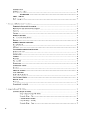
... drives ...20 SATA hard drive cables ...20 SATA data cable ...20 SMART ATA drives ...21 Cable management ...21 4 Removal and Replacement Procedures ...23 Preparing to disassemble the computer ...23 Removing the rear covers from the computer ...24 Hard drive ...26 Memory ...29 Wireless USB receiver ...31 M.2 cover and solid-state drive...
... drives ...20 SATA hard drive cables ...20 SATA data cable ...20 SMART ATA drives ...21 Cable management ...21 4 Removal and Replacement Procedures ...23 Preparing to disassemble the computer ...23 Removing the rear covers from the computer ...24 Hard drive ...26 Memory ...29 Wireless USB receiver ...31 M.2 cover and solid-state drive...
Maintenance & Service Guide
Page 25
... procedures and precautions described in this chapter is plugged into many integrated circuits provide some protection, but in the internal layers, reducing its life expectancy. 3 Disassembly preparation and SATA drive guidelines This chapter provides general service information for proper service.
... procedures and precautions described in this chapter is plugged into many integrated circuits provide some protection, but in the internal layers, reducing its life expectancy. 3 Disassembly preparation and SATA drive guidelines This chapter provides general service information for proper service.
Maintenance & Service Guide
Page 26
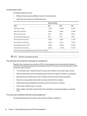
... contact, transport products in static-safe containers such as humidity decreases. Preventing electrostatic damage to equipment Many electronic components are sensitive to equipment: 16 Chapter 3 Disassembly preparation and SATA drive guidelines Circuitry design and structure determine the degree of bench worker 400 V Removing DIPs from plastic tube 400 V Removing DIPs from...
... contact, transport products in static-safe containers such as humidity decreases. Preventing electrostatic damage to equipment Many electronic components are sensitive to equipment: 16 Chapter 3 Disassembly preparation and SATA drive guidelines Circuitry design and structure determine the degree of bench worker 400 V Removing DIPs from plastic tube 400 V Removing DIPs from...
Maintenance & Service Guide
Page 28
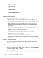
... cold. ● Operate the computer on the monitor with the covers or panels removed. ● If the computer is in mind during the disassembly and assembly of the computer. Do not place the keyboard, with the keyboard feet down, directly against the front of the desktop unit as this... on a sturdy, level surface. Be sure to unplug the computer before opening the computer to prevent system board or component damage. 18 Chapter 3 Disassembly preparation and SATA drive guidelines The cooling fan is off when the computer is to be provided on all vented sides of the computer. ●...
... cold. ● Operate the computer on the monitor with the covers or panels removed. ● If the computer is in mind during the disassembly and assembly of the computer. Do not place the keyboard, with the keyboard feet down, directly against the front of the desktop unit as this... on a sturdy, level surface. Be sure to unplug the computer before opening the computer to prevent system board or component damage. 18 Chapter 3 Disassembly preparation and SATA drive guidelines The cooling fan is off when the computer is to be provided on all vented sides of the computer. ●...
Maintenance & Service Guide
Page 29
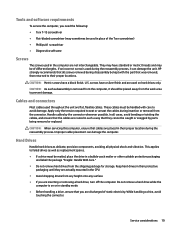
... way that the cables are not interchangeable. CAUTION: When servicing this computer, ensure that was removed, then returned to their proper location during disassembly be handled with the part that cables are inserting or removing a hard drive, turn off the computer. Do not remove a hard drive... while the computer is on hard drives only. HP strongly recommends that you are placed in standby mode. ● Before handling a drive, ensure that all screws removed during the reassembly process. ...
... way that the cables are not interchangeable. CAUTION: When servicing this computer, ensure that was removed, then returned to their proper location during disassembly be handled with the part that cables are inserting or removing a hard drive, turn off the computer. Do not remove a hard drive... while the computer is on hard drives only. HP strongly recommends that you are placed in standby mode. ● Before handling a drive, ensure that all screws removed during the reassembly process. ...
Maintenance & Service Guide
Page 30
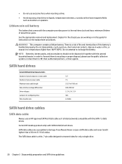
...the general household waste. See the appropriate removal and replacement chapter for the chassis you are susceptible to recharge the battery. WARNING! Current HP desktop products ship with the SATA 1.5 Gb/s drives. Lithium coin cell battery The battery that have magnetic fields such as it is...collection system or return them to transmit data for instructions on the replacement procedures. Do not attempt to damage if overflexed. Do not disassemble, crush, puncture, short external contacts, dispose in water or fire, or expose it tighter than 140ºF (60ºC). SATA...
...the general household waste. See the appropriate removal and replacement chapter for the chassis you are susceptible to recharge the battery. WARNING! Current HP desktop products ship with the SATA 1.5 Gb/s drives. Lithium coin cell battery The battery that have magnetic fields such as it is...collection system or return them to transmit data for instructions on the replacement procedures. Do not attempt to damage if overflexed. Do not disassemble, crush, puncture, short external contacts, dispose in water or fire, or expose it tighter than 140ºF (60ºC). SATA...

Maintenance & Service Guide
Page 32
22 Chapter 3 Disassembly preparation and SATA drive guidelines
22 Chapter 3 Disassembly preparation and SATA drive guidelines
Maintenance & Service Guide
Page 33
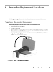
...the front of sharp edges inside the chassis. WARNING! Preparing to disassemble the computer To avoid injury and equipment damage, always complete the following sections provide information about disassembling various components of the computer. 4. Remove all attached cables from the... computer. 2. Preparing to disassemble the computer 23 Shut down on a flat surface covered with a soft ...
...the front of sharp edges inside the chassis. WARNING! Preparing to disassemble the computer To avoid injury and equipment damage, always complete the following sections provide information about disassembling various components of the computer. 4. Remove all attached cables from the... computer. 2. Preparing to disassemble the computer 23 Shut down on a flat surface covered with a soft ...

Maintenance & Service Guide
Page 34
... (1). 3. Locate the recess in the bottom of the cover (2), and then lift and rotate the outside of the cover up to disassemble the computer on page 23). 2. Prepare the computer for disassembly (see Preparing to disengage it from the chassis (3). 24 Chapter 4 Removal and Replacement Procedures Locate the recess in the bottom...
... (1). 3. Locate the recess in the bottom of the cover (2), and then lift and rotate the outside of the cover up to disassemble the computer on page 23). 2. Prepare the computer for disassembly (see Preparing to disengage it from the chassis (3). 24 Chapter 4 Removal and Replacement Procedures Locate the recess in the bottom...
Maintenance & Service Guide
Page 36
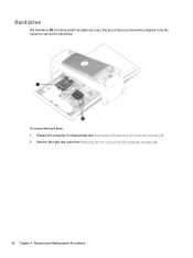
Prepare the computer for disassembly (see Removing the rear covers from the column to disassemble the computer on page 24). 26 Chapter 4 Removal and Replacement Procedures To remove the hard drive: 1. You do not have to remove the computer from the computer on page 23). 2. Remove the right rear cover (see Preparing to service the hard drive. Hard drive The hard drive (1) is located under the right rear cover.
Prepare the computer for disassembly (see Removing the rear covers from the column to disassemble the computer on page 24). 26 Chapter 4 Removal and Replacement Procedures To remove the hard drive: 1. You do not have to remove the computer from the computer on page 23). 2. Remove the right rear cover (see Preparing to service the hard drive. Hard drive The hard drive (1) is located under the right rear cover.
Maintenance & Service Guide
Page 39
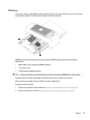
... ● 16 GB maximum installable memory NOTE: Because the memory uses dual channels, you must use the same SODIMM type for disassembly (see Removing the rear covers from the column to disassemble the computer on page 23). 2. To remove a memory module: 1. Memory Two memory module sockets (2) are small outline dual-inline memory...
... ● 16 GB maximum installable memory NOTE: Because the memory uses dual channels, you must use the same SODIMM type for disassembly (see Removing the rear covers from the column to disassemble the computer on page 23). 2. To remove a memory module: 1. Memory Two memory module sockets (2) are small outline dual-inline memory...
Maintenance & Service Guide
Page 41
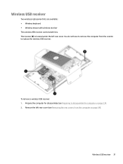
... wireless receiver The wireless USB receiver controls both kits. Remove the left rear cover. Wireless USB receiver 31 Prepare the computer for disassembly (see Removing the rear covers from the column to disassemble the computer on page 24). You do not have to remove the computer from the computer on page 23). 2.
... wireless receiver The wireless USB receiver controls both kits. Remove the left rear cover. Wireless USB receiver 31 Prepare the computer for disassembly (see Removing the rear covers from the column to disassemble the computer on page 24). You do not have to remove the computer from the computer on page 23). 2.
Maintenance & Service Guide
Page 43
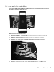
Prepare the computer for disassembly (see Removing the rear covers from the computer on page 23). 2. Remove the Phillips M2.0×3.0 screw (1) that secures the solid-state drive to replace ... M.2 cover (1), and then lift the cover off the computer (2). 4. To remove the M.2 cover and solid-state drive: 1. Remove the left rear cover (see Preparing to disassemble the computer on page 24). 3. M.2 cover and solid-state drive 33
Prepare the computer for disassembly (see Removing the rear covers from the computer on page 23). 2. Remove the Phillips M2.0×3.0 screw (1) that secures the solid-state drive to replace ... M.2 cover (1), and then lift the cover off the computer (2). 4. To remove the M.2 cover and solid-state drive: 1. Remove the left rear cover (see Preparing to disassemble the computer on page 24). 3. M.2 cover and solid-state drive 33
Maintenance & Service Guide
Page 45
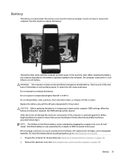
... extended by briefly touching a grounded metal object. Battery The battery is not handled properly. The computer comes with the HP spare designated for disassembly (see Removing the rear covers from the column to AC power. NOTE: The lifetime of the lithium battery can damage...see Preparing to back up the computer CMOS settings. Prepare the computer for this product. Do not expose to http://www.hp.com/recycle. 1. Do not disassemble, crush, puncture, short external contacts, or dispose of the computer or optional equipment. Static electricity can be cleared. ...
... extended by briefly touching a grounded metal object. Battery The battery is not handled properly. The computer comes with the HP spare designated for disassembly (see Removing the rear covers from the column to AC power. NOTE: The lifetime of the lithium battery can damage...see Preparing to back up the computer CMOS settings. Prepare the computer for this product. Do not expose to http://www.hp.com/recycle. 1. Do not disassemble, crush, puncture, short external contacts, or dispose of the computer or optional equipment. Static electricity can be cleared. ...
Maintenance & Service Guide
Page 47
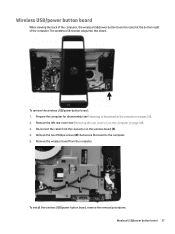
To remove the wireless USB/power button board: 1. Remove the two Phillips screws (2) that secure the board to disassemble the computer on the wireless board (1). 4. Remove the wireless board from the connector on page 23). 2. Wireless USB/power button board When viewing the back... USB/power button board is located at the bottom right of the computer. The wireless USB receiver plugs into this board. Prepare the computer for disassembly (see Removing the rear covers from the computer on page 24). 3. Disconnect the cable from the computer. To install the wireless USB/power button ...
To remove the wireless USB/power button board: 1. Remove the two Phillips screws (2) that secure the board to disassemble the computer on the wireless board (1). 4. Remove the wireless board from the connector on page 23). 2. Wireless USB/power button board When viewing the back... USB/power button board is located at the bottom right of the computer. The wireless USB receiver plugs into this board. Prepare the computer for disassembly (see Removing the rear covers from the computer on page 24). 3. Disconnect the cable from the computer. To install the wireless USB/power button ...
Maintenance & Service Guide
Page 48
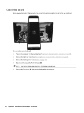
Prepare the computer for disassembly (see Preparing to the computer. 38 Chapter 4 Removal and Replacement Procedures Disconnect the two cables from the computer on page 23). 2. Remove the right rear ... is located to the display manufacturer. 5. Converter board When viewing the back of the system board. Remove the Torx screw (2) that secures the board to disassemble the computer on page 24). 3. To remove the converter board: 1.
Prepare the computer for disassembly (see Preparing to the computer. 38 Chapter 4 Removal and Replacement Procedures Disconnect the two cables from the computer on page 23). 2. Remove the right rear ... is located to the display manufacturer. 5. Converter board When viewing the back of the system board. Remove the Torx screw (2) that secures the board to disassemble the computer on page 24). 3. To remove the converter board: 1.
Maintenance & Service Guide
Page 50
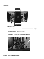
Prepare the computer for disassembly (see Preparing to disassemble the computer on page 29). 4. Disconnect the two cables from the computer. Lift the USB board from the board (1). 5. USB board When viewing the back ...
Prepare the computer for disassembly (see Preparing to disassemble the computer on page 29). 4. Disconnect the two cables from the computer. Lift the USB board from the board (1). 5. USB board When viewing the back ...
Maintenance & Service Guide
Page 51
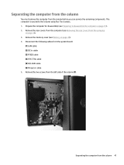
... rear covers from the computer (see Removing the rear covers from the computer on page 29). 4. The computer is secured to disassemble the computer on page 23). 2. Prepare the computer for disassembly (see Memory on page 24). 3. Remove the two screws from the system board: (1) LAN cable (2) DC In cable (3) POGO cable...
... rear covers from the computer (see Removing the rear covers from the computer on page 29). 4. The computer is secured to disassemble the computer on page 23). 2. Prepare the computer for disassembly (see Memory on page 24). 3. Remove the two screws from the system board: (1) LAN cable (2) DC In cable (3) POGO cable...


